|
|
 |
Using the Make Subcircuit Option
There are two model types within Micro-Cap that let the behavior of a complex circuit block be incorporated
into and represented by a single component in a schematic. These model types are the macro and the
subcircuit. The main difference between these two types is that a macro has its circuitry defined through
a schematic whereas the subcircuit has its circuitry defined through a SPICE text netlist.
While the macro is typically the easier model type to create, it is limited to use in only the Micro-Cap
simulator. Though the text description of a subcircuit model is more difficult to develop, a subcircuit
can be transferred to any other application that is capable of handling the SPICE netlist format. This
portability is the main advantage to using a subcircuit model.
To ease the difficulties in creating a SPICE netlist, Micro-Cap provides a translation feature to convert
schematic files into SPICE netlists. One of the options within this translate to SPICE feature is the
ability to create a subcircuit model out of the schematic rather than the full SPICE circuit file that
is normally produced. This article will describe the process of taking a schematic and converting it
into its subcircuit equivalent.
The first step is to create the schematic that will represent the appropriate model. The schematic
should only contain the components that will be part of the model as all of the components within the
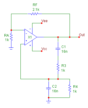
schematic will be incorporated into the subcircuit. For this example, the schematic to be used appears
below. This schematic models a basic Wien bridge oscillator that produces about a 9kHz output sine wave.
The desired input and output nodes for the model have been labelled with text. The power supplies for the
opamp have been called Vcc and Vee, and the output is simply labelled Out.
|

|
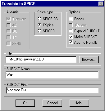
Once the schematic is ready, click on the File menu, select Translate and choose the Schematic to SPICE Text
File option. The Translate to SPICE dialog box that is invoked is displayed in the figure below.
|

|
Enabling the Make SUBCKT in the Options section will force the translation to create a subcircuit model in
a library file. Both the Analysis section and the .Options option will be disabled since these are only
available for a full circuit netlist.
The Spice type section determines the SPICE format that the subcircuit will be created in. The three
options are: SPICE 2G, PSpice, and SPICE3. The selection here would depend on the type of syntax that
any other programs that may access the subcircuit can handle. Micro-Cap is capable of handling all three
of these formats.
The Report option will place a section of comments in the library file detailing the components that
the subcircuit is comprised of. This will have no effect on the actual operation of the subcircuit. The
Expand SUBCKT option will place all subcircuit or macro models that the active schematic references into
the library file as separate subcircuit models. This option localizes all the model information for the
main subcircuit model into the specified library file. The Add To Nom.lib option will add a reference for
the library file that is being created into the NOM.LIB file. The NOM.LIB file contains a list of library
files that Micro-Cap will automatically access. This option should be enabled if the new subcircuit model
may be used within Micro-Cap.
The File field contains the path and name of the library file to be created. For Micro-Cap use, the library
file should be created with a .LIB extension.
The SUBCKT Name field specifies the name of the subcircuit model. The name must be a single string with
no spaces.
The SUBCKT Pins field defines the nodes that the subcircuit will use for its input and output connection
pins. The pins should be node names or node numbers from the schematic and should be separated by commas
or spaces in the list. If you have named the node in the schematic with a text label, you must use the
name rather than the corresponding node number since the text name has priority when the translation
occurs.
Clicking on the OK button initiates the translation with the specified settings. The new library file
will then be loaded in Micro-Cap. For the Wien Bridge Oscillator example, the subcircuit produced is:
.SUBCKT Wien Vcc Vee Out
C1 Out 4 16N
C2 3 0 16N
R3 3 4 1K
R4 0 3 1K
RA 0 1 1K
RF 1 Out 2.1K
X1 3 1 Vcc Vee Out UA741_TI
.ENDS Wien
Note that in the .SUBCKT line above the name of the model is Wien and the pin names are Vcc, Vee, and Out
as was specified in the Translate to SPICE dialog box. To include the UA741_TI model that the Wien subcircuit
references in the same library file, the Expand SUBCKT options would have needed to be enabled.
When the Make SUBCKT option is selected, the translation will also create an entry for the new subcircuit
in the component library so that this part will be available for placement in a schematic. The new entry
is placed in the SUBCKT.CMP file in the main MC8 directory, and the component will now be accessible through
a Subckt group on the first level of the Component menu.
Since Micro-Cap does not inherently know the function of the subcircuit, the new component entry uses the
AutoMacro shape. This shape provides a resizeable rectangle where the pins can be moved through a drag
operation. Typically, one would want to edit the entry so that it uses a more recognizable shape that
exists in the shape library prior to placing this part in a schematic. To do this, just enter the Component
Editor, and select the entry that was created for this subcircuit. It will be present in the Subckt.cmp
section of the component tree on the right hand side of the dialog box. Once selected, just change the
Shape reference for the part and then move the pin connections to the appropriate parts of the shape.
If none of the existing shapes are appropriate for the subcircuit, a new shape would need to be created
in the Shape Editor.
Assuming the Add To Nom.lib option was enabled for the translation, this subcircuit is now ready to be
used in a Micro-Cap simulation. If the Add To Nom.lib was disabled, the Nom.lib file would then need
to be manually edited or an explicit reference to the new library, such as with a .lib statement, would
need to be defined in the schematic that is using the subcircuit component before this subcircuit would
be available for simulation.
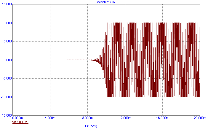
A simple test circuit has been set up to test the Wien bridge oscillator. Fixed Analog components have been
used to place twelve volts at the Vcc pin and minus twelve volts at the Vee pin. The transient analysis
output of the oscillator is displayed below.
|

|
The transient simulation has been run over a time range of 20ms. The output produces a sine wave shape whose
peaks and valleys are flattened due to saturation at the output rails of the UA741 opamp referenced within
the oscillator. The output frequency of the sine wave is measured to be approximately 8.74kHz.
|
|
|
|
|


