|
|
 |
Voltage Limiting Current Source Macro
The SPICE constant current source available in Micro-Cap is an ideal source. It will produce the specified
current throughout the simulation run. This means that the voltage across the source needs to have an
infinite range since the specified current must be generated for any topology. This feature of the current
source has the potential of creating unrealistic voltages across the source. For some applications,
introducing a current model that has voltage limitation capabilities can be a good improvement. The
voltage limiting current source macro derived below is based on a model created by Ray Kendall which is
described in the article "SPICE model mimics realistic current source" in the EDN Design Ideas Supplement
of June 22, 1995.
|

|
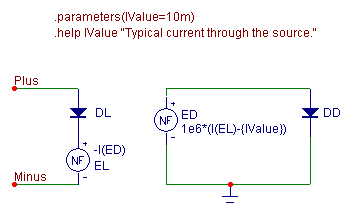
The voltage limiting current source macro circuit is shown above. This macro takes a single parameter,
IValue, which defines the typical current that will flow through the source when the voltage is not being
limited. The macro circuit consists of two nonlinear function voltage (NFV) sources and two diodes. The
current between the Plus and Minus pins is determined through an iterative process between the NFV sources
EL and ED. The ED function source is defined with the equation:
1e6*(I(EL)-{IValue})
which looks at the difference between the current flowing between the Plus and Minus pins and the current
value specified as the input parameter. The source then multiplies this difference by a large gain in
order to forward bias the DD diode. The EL function source is defined with the equation:
-I(ED)
which produces a voltage in the EL source equivalent to the negative value of the current flowing through
the ED source. The iterative process works such that the current produced in the ED source and DD diode
loop will be equivalent to the voltage offset needed for the EL source to create a voltage drop across the
DL diode that will cause a current of IValue amps to flow through the diode.
The actual current that will flow through the source will be slightly different than the IValue specified.
The size of the difference depends on the gain value used in the ED source equation. For a 20mA source, with
the gain set to 1e6, the actual current in the source will be around 20.001mA. To accurately simulate
smaller currents with this source, the gain value should be increased accordingly to minimize the
difference.
The voltage limitation capabilities of the source are due to the presence of the diodes. The DD diode ensures
that the current in the loop will flow in only one direction. This prevents the EL source from producing a
negative voltage, so that the current source will be shut down if the differential voltage across it becomes
smaller than the diode drop needed to produce the specified current value.
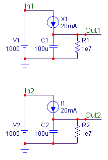
An example schematic for the macro appears below. The schematic contains two circuits. One uses the
current source macro and the other uses the ISource component. Both of these sources have been defined as a
20mA current source. Each circuit is powered with a 1000V battery. The sources are used to charge a 100uF
capacitor at the output.
|

|
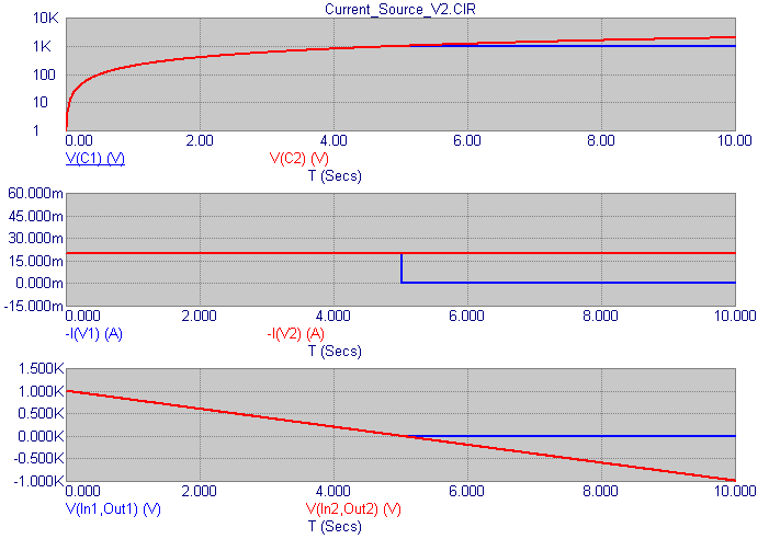
The transient analysis results for this schematic is displayed below. The blue waveforms are from the circuit
using the current source macro, and the red waveforms are from the circuit using the ISource component.
For the first half of the simulation, the waveforms match as each capacitor charges up to 1000 volts. As soon
as the capacitors hit the 1000 volt mark halfway through the simulation, the waveforms diverge as shown in
the plots. At this point, the current source macro shuts itself off as there is essentially zero voltage
across it. Note in the middle plot that the current through the source drops from 20mA to approximately 0A
when this occurs, and in the bottom plot, the voltage across the current source macro, V(In1,Out1), limits
at approximately 0V.
For the ideal source, since it will continually produce the 20mA through the whole simulation, the capacitor
continues to charge even though it has exceeded the battery voltage. By the end of the simulation, the C2
capacitor actually has 2kV across it. In order to do this, the ideal current source has to produce a
negative voltage across itself.
While the ideal current source is fine for most applications, it is simulations such as this one in which
the voltage limiting current source macro provides an analysis that would be more in line with real world
expectations.
|

|
|
|
|
|


