|
|
 |
Repeater Macro
The repeater macro provides the capability to take a one shot waveform and give it a
periodic characteristic. For some waveform sources, such as the User source, creating
a periodic waveform requires a lot of data to be generated in order to produce the
waveform over the time range that is being simulated. Rather than creating multiple
cycles in the User source file, only one cycle needs to be created when the source is
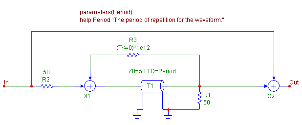
used in conjuction with the repeater macro. The repeater macro is shown below.
|

|
The repeater macro takes in one parameter: Period. This defines the period of the input
waveform that is to be repeated. The repeater macro consists of three resistors, two Sum
macros, and a lossless transmission line. The R1 and R2 resistors along with the T1
transmission line produce a delay element whose delay is defined by the parameter Period.
The input signal is fed into the two Sum macros. The original waveform will be passed
directly to the Sum macro at the output and produce the expected waveform during the first
Period seconds. The input is also passed into the delay element through the Sum macro at
the input. After Period seconds have passed, the original waveform now starts to appear at
the output of the transmission line and is reproduced at the output of the macro. This
waveform is also fed back into the input of the delay element so that the cycle will repeat
continuously. The R3 resistor in the feedback loop has had its VALUE attribute defined
as:
(T<=0)*1e12
which will produce a 1E12 resistor when the simulation time is zero or negative, and a
RMIN (set in the Global Settings) valued resistor when the simulation time is greater
than 0. The high resistance at time=0 helps prevent a positive feedback loop from
occurring during an operating point calculation.
In order for the repeater macro to work correctly, the input waveform must be at zero once
the time of the original period has passed. Any nonzero voltages after the original period
has expired will be passed to the output and be summed with the original waveform. If a
DC voltage is passed through, a ladder effect will occur where each subsequent period is
greater than the previous by the value of the DC voltage. Also, this macro does not work
in DC so a DC or Dynamic DC analysis will not converge when this macro is used in a
circuit. For transient analysis, the operating point should generally be disabled.
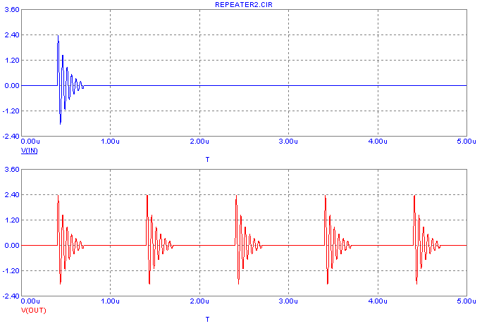
A simple circuit was set up to test the repeater macro. It consisted of a User source
connected to the input of the repeater macro. The User source imports in the SAMPLE.USR
file that is distributed with Micro-Cap. The SAMPLE.USR file has 1us worth of data
stored in the file and simulates a few cycles of a damped sine wave. The repeater macro
has its Period parameter set to 1u. The resulting transient analysis for a 5us
simulation is displayed below.
|

|
The top waveform is the waveform directly from the User source. It simulates the 1us of
data within the file and then stays at zero volts for the rest of the simulation. The
bottom waveform is the output of the repeater macro. Note that it has taken the 1us of
data from the User source and has turned it into a periodic waveform with a period of 1us.
|
|
|
|
|


