|
|
 |
Introducing Micro-Cap 8
We are pleased to release the next generation of the Micro-Cap simulator, Micro-Cap 8.0.
A number of new features, components, and models have been added to enhance the simulation
power and the ease of use of the interface. A preview of some of the new features
follows. Please contact our sales department for upgrade or pricing questions.
New MOSFET Models - BSIM4 and EKV
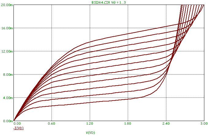
Two new MOSFET models have been incorporated into MC8. The first is the BSIM4 device
which is a level 14 MOSFET. This model was created at Berkeley and is designed to
address MOSFET physical effects into the sub-100nm realm. The second model is the
EKV MOSFET model (level 44) from the Swiss Institute of Technology. It features a
dedicated charge-based short channel dynamic model using only 18 intrinsic core
parameters.
|
|
HSPICE Style Binning
Binning is the process of adjusting model parameters for different values of drawn channel
length (L) and width (W). BSIM3 and BSIM4 MOSFET devices were upgraded to include
the HSPICE binning option, as well as the standard Berkeley binning option.
Short Distance VT Matching for BSIM3, BSIM4, and EKV Models
The BSIM3, BSIM4, and EKV models were upgraded to include a short distance VT matching
parameter, to better model short distance threshold variations.
IBIS Modeling Tool
IBIS is an acronym for Input Output Buffer Information Specification. It is a method
of describing device characteristics at the input/output level without having to
describe the possibly proprietary circuitry that produce the characteristics. It
can be thought of as a kind of behavioral modeling specification suitable for
transmission line simulation of digital systems and applicable to most digital
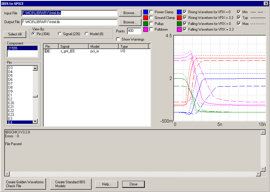
components. New IBIS modeling tools were added to translate IBIS files to standard
Micro-Cap / SPICE input and output pin models. These models accurately reproduce the
IBIS golden waveforms. The IBIS editor creates both standard library SPICE models and
verification models for testing and verifying golden waveforms.
|
|
SPICE Voltage and Current Source Enhancements
New time-domain Noise and Gaussian waveforms and user definable preset tabs for common
waveform settings were added to make complex waveform creation easy.
Timer Device
A flexible new timer device was added to count events, and to measure both elapsed and
last event time. Attributes set the initial, minimum, and maximum count along with
the increment value. A reset pin is also available on the device.
Enhanced S and W Switches
A hysteresis option was added to the S (Voltage) and W (Current) switches.
Improved Magnetics Model
A new, more robust Jiles-Atherton magnetics model was added. Both MODEL and the
mainline simulator can plot BH values in both CGS and MKS (SI) units. The
convergence routines for gapped cores has been vastly improved.
N-Port Device Using Touchstone Data Format
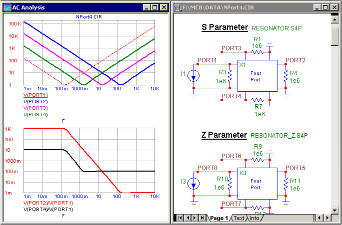
The N-Port model in MC8 provides a way to easily include S, Y, Z, G, or H parameter
data from RF suppliers in a simulation. The N-Port model imports in a Touchstone
data file containing tables of data that define the specified parameter values
versus frequency. While the 2-Port is the most common use of a Touchstone file,
any number of ports may be imported in Micro-Cap. These text files are available
from many companies such as Siemens and Infineon. With the capability to produce
Smith charts and polar plots in AC analysis, creating plots of data such as S parameters
is easier and more powerful than ever. Micro-Cap also contains a translator that provides
the capability to convert Touchstone files from one parameter format to another.
|
|
Subcircuit Maker
A new Make SUBCKT command translates a schematic to a SPICE subcircuit. The subcircuit
will automatically be added to the Component library of Micro-Cap for use in other
schematics.
Improved Bill of Materials Report
A new Bill of Materials report features sorting on any field and a live report that
responds to user format changes immediately.
New Graphic Formats
TIFF, PNG, JPG, and GIF graphics formats were added to the standard BMP, WMF, and EMF
formats for saving schematic and plot images to a file. These new formats may also be
used when placing graphic files into a schematic.
Component Menu Shape Display
The Component menu now shows the component shape as you browse as a preview of what the
component will look like in the schematic.
Animation Components
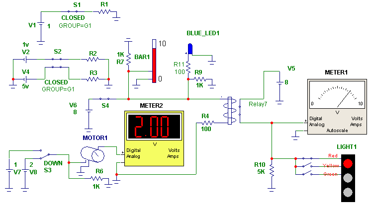
Many new animation components have been added to MC8, and all of the animation
components have been enhanced to work with the Dynamic DC analysis. The new
components are:
SPST, DPDT, DPST analog switches for dynamically configuring a circuit.
Analog bar with height proportional to the input DC voltage.
Analog LED with user-defined color and on voltage.
Rotating DC motor with DC voltage dependent RPM.
Analog / digital DC voltage/current meter.
Relay with programmable resistance, inductance, and on and off currents.
Three color traffic light.
|
|
Password Protection
A new protection feature added password protection to circuit and macro files. Another
user may simulate a circuit with a macro that has been password protected, but they
will be unable to view the inner workings of the macro.
Find in Files Command
A new Find in Files command was added to search circuit or other files for text,
components, or other content. This is particularly useful if you remember a
specific component or text string used in a circuit, but are unable to recall the
actual circuit name.
Info Page
An Info text page was added to show the location of models, macros, subcircuits, or
variables used in the circuit, resolving uncertainty over the source of the device
model or variable.
Cleanup Command
A new Cleanup command for deleting miscellaneous extraneous files was added. This
feature provides an easy way to delete files such as numeric output or probe files
that may not be needed anymore from the hard drive.
Local Path Commands
New local .PATH commands let a circuit specify DATA and LIBRARY paths, overriding the
global paths. This feature lets you store the path information locally within a
circuit.
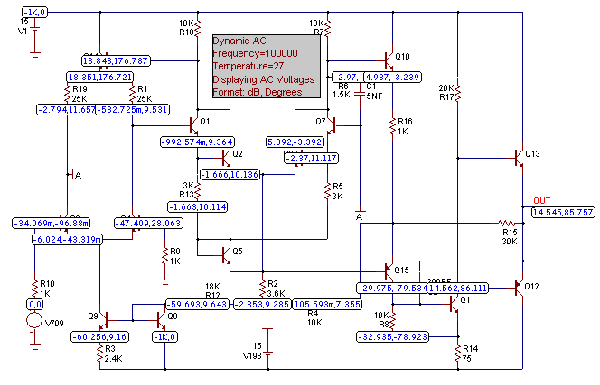
New Dynamic AC Analysis
A new analysis mode was added that features dynamic on-schematic display of AC
voltage, current, and power as frequency is stepped, with the display dynamically
responding to schematic edits.
|
|
Enhanced Dynamic DC Analysis
Stepping, optimization, and an Analysis Limits dialog box were added to Dynamic DC.
Apply Display Properties Command
A new command was added to copy a selected part’s display properties (part color,
attribute font, size, color, and print location) to other similarly named and
rotated parts.
Change Attribute Command
A new Change Attribute command was added to add, delete, edit, show, or hide attributes
of any subset of the parts in a schematic, making mass changes easy.
New Color Options
Parts and wires can now have individual colors in a schematic.
New Attribute Dialog Box Plot
Diodes acquired a new Ir vs. Vr plot to show reverse characteristics within the
Attribute dialog box.
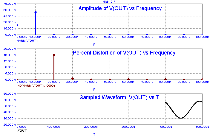
New Distortion Analysis
A new analysis mode was added that employs the DSP routines to calculate and plot
measures of distortion, including raw harmonics, as well as total and individual
harmonic distortion. Distortion analysis is a type of transient analysis that
applies a single frequency sinusoidal signal to the named input source and measures
the resulting distortion in the specified output expression using the IHD (Individual
Harmonic Distortion) function.
|
|
Enhanced Fourier Analysis
A new FFT window was added to automatically convert transient plots to Fourier plots.
This conversion is performed after the simulation is finished running so there is no
need to specify the FFT function before the run to view harmonic information. A new
FS(expr,n1,n2) function was added that creates a waveform from the n1 to n2 terms of
the Fourier series of (expr). A new RES(expr,n1,n2) function was added to create a
residual waveform by subtracting the n1 to n2 terms of the original waveform. FFT
auto-scale commands were upgraded to allow ignoring the DC component and auto
scaling over only a specified number of harmonics.
Analysis Limits Dialog Box
The dialog box size and X and Y fields are user-adjustable.
Optimizer Enhancements
The new optimizer supports dynamic plots to show optimization progress and works with
both Dynamic DC and Dynamic AC.
Analysis Plot Improvements
Scale factors (Meg, K,...p, f) for X/Y axes. e.g. “Time (nS)”
Units (Amps, Volts, Watts,...) for plots. e.g. “V(26) (Volts)”
Open and closed circles and squares data point markers
Normal and popsicle data point styles
X, Y, or both auto scaling options
New option to force all X scales to be the same
Retrace mode for rolling displays
Right clicking on expressions to invoke FFT, performance, and 3D plots
New minor log grid option to show and label 1-2-5-10 sequence
New Expressions and Functions
Integration and differentiation operators for use in function sources
Array variables for indexed selection of variable values from a predefined array of values
Transmission line power and energy terms
AC power and energy terms
New random functions, RNDR, RNDC, and RNDI(interval)
New DELAY(x,d) function returns expression x delayed by d seconds
S and W switch resistance, voltage, current, power, and energy terms
SPICE3 analog Boolean operators, &, |, ~, and ^ with analog parameters
LAST(expr,n) function which returns a value from n data points before
MAXR and MINR function to track an expression’s highest and lowest value during a run
NORM, NORMMAX and NORMMIN functions to normalize at specified, maximum, and minimum points
International engineering notation (e.g. 3R3 = 3.3)
Global settings variables
Model parameter use of variables like TEMP that are constant during a run
Nested series expressions
Product series function (e.g. PROD(I,1,3,I) = 1*2*3)
MODEL Import
MODEL provides one step exporting of its parts directly to the Component library.
Numeric Formats
A new decimal numeric format uses only numbers, commas, and decimal points.
1.234e6 can be formatted as 1,234,000.00. Support added for international engineering
notation (e.g. 3R3 = 3.3).
Filter Designer Improvements
Step and Impulse response plots were added.
Monte Carlo Improvements
A new feature lets users reproduce statistical distributions by specifying the random
number seed. New features included user-specified histogram range and intervals.
Expanded LAN Operation
Several features were added to better support LAN installations. The model library
index is now written locally, avoiding the need to write to possibly write-protected
LAN disks. Component, Shape, and Package library files could also be located on
write-protected LAN disks.
Miscellaneous
New .WARNING message, condition command to let users create custom warnings such as .WARNING “Capacitor voltage exceeded.” V(C1) > 50
SPACEBAR toggle between voltage and current in Probe.
DEFINE statement for use in SPICE files.
All On and All Off buttons to enable/disable all stepped variables.
Rename command to provide left to right and top to bottom options.
Translator to convert file from S, Y, Z, G, or H format to any other format.
New numeric output options let the user decide what to include.
|
|
|
|
|


