|
|
 |
A UC1845 Macro Model
A recent article in the March 7, 2002 issue of EDN, entitled "Modular macromodeling techniques for SPICE simulators", illustrated a very workable model for the UC1845 Pulse width modulator. We have implemented the model in Micro-Cap and expanded it to model the full line of UCX84X PWMs. This article describes the details.
Altogether, twelve parts are modeled:
UC1842, UC1843, UC1844, UC1845
UC2842, UC2843, UC2844, UC2845
UC3842, UC3843, UC3844, UC3845
The three UCX84X families are similar. Within each series, the UCXX44 and UCXX45 use an internal T flip-flop to divide down the internal oscillator to provide for differing duty cycles, while the others do not. The UCX842 and UCX844 sets the acceptable VCC range at 10-16 volts while the UCX843 and UCX845 have the acceptable VCC range set at 7.6-8.4 volts.
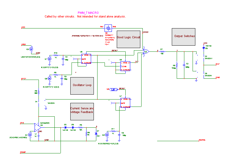
Two basic macros are used to implement the entire line of parts, the PWM_T and the PWM_NT. Here is the PWM_T macro which uses the T Flip-flop.
|

|
The Good Logic section uses the Schmitt macro to produce a logic 1 when the VCC line has the desired voltage range. This signal is provided to the external pin and also enables the output switches
Here is its twin, the PWM_NT. The only difference is the absence of the T Flip-flop.
|
Here is the boost regulator test circuit from the EDN article. The circuit has been elaborated a little to add a pulse source on the VCC line to test the model's response to changes in the VCC line voltage.
|
Here is the transient analysis of the circuit, showing the regulated output and the shutdown of regulation when the VCC voltage goes out of bounds, along with the Good VCC signal.
|
|
|
|
|


