|
|
 |
Thermistor Macro
A thermistor is a thermally sensitive resistor that changes its resistance with changes in temperature in a predictable manner. Thermistors are used for such applications as temperature measurement, temperature control, power measurement, amplitude stabilization, and timing circuits. The following macro model was derived from a design idea by Lutz Wangenheim titled "SPICE Subcircuit Models Thermistors" in the July 3, 1997 issue of EDN.
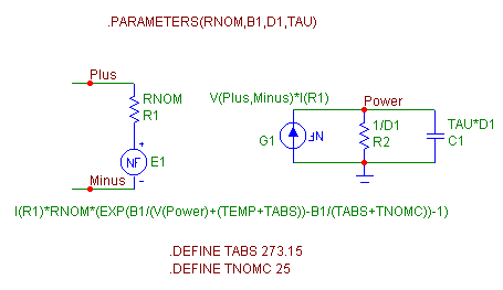
The macro circuit for the thermistor appears below. The macro was derived from the basic resistance-temperature equation used to describe thermistors which is as follows:
R = Rnom*exp(B1/T - B1/Tnom)
where R is the resistance of the thermistor, Rnom is the nominal resistance, B1 is the material constant, T is the thermistor body temperature, and Tnom is the nominal temperature.
|

|
The macro has four parameters: RNOM, B1, D1, and TAU. RNOM defines the nominal resistance at the nominal temperature. B1 defines the material constant. D1 defines the thermistor's dissipation factor. TAU defines the thermal time constant of the thermistor body. The R1 resistor and the E1 NFV source model the resistance of the thermistor. The R1 resistor has its VALUE attribute defined as RNOM and models the nominal resistance. The E1 source takes into account the ambient temperature and the power dependent portion of the temperature to adjust the equivalent resistance of the thermistor. The thermistor's equivalent resistance is equal to:
R = RNOM + V(E1)/I(R1)
replacing R with the first equation and solving for V(E1) returns:
V(E1) = I(R1)*RNOM*(exp(B1/T - B1/Tnom) - 1)
To model this equation, the E1 source has its VALUE attribute defined as:
I(R1)*RNOM*(EXP(B1/(V(Power)+(TEMP+TABS))-B1/(TABS+TNOMC))-1)
The nominal temperature is represented by the TABS + TNOMC equation. This equation uses the two .define statements in the macro to produce an equivalent Kelvin temperature value from the specified measurement temperature TNOMC in Celsius. To edit the nominal temperature of the thermistor macro, simply edit the .define statement for TNOMC.
The thermistor body temperature is represented by the V(Power)+(TEMP+TABS) equation. V(Power) models the power dependent portion of the temperature due to internal heating. It is generated from the G1 NFI source, the R2 resistor, and the C1 capacitor. The G1 NFI source calculates the power between the thermistor's Plus and Minus pins and produces an equivalent current. The R2 resistor is defined with a value equal to the reciprocal of the thermistor's dissipation factor, and the C1 capacitor models the thermal time constant in conjunction with the R2 resistor. (TEMP+TABS) models the ambient temperature. TEMP is the temperature variable that is defined in the Temperature text field in the Analysis limits dialog box. TABS is defined as 273.15 and converts the specified TEMP variable from Celsius to Kelvin.
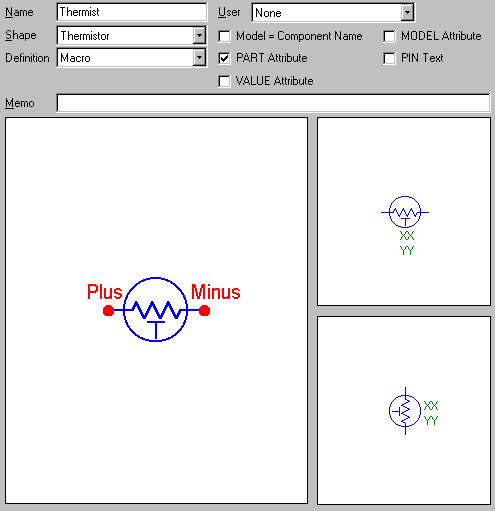
The Component Editor settings for the thermistor macro appear below. The Name has been defined as Thermist to match the macro circuit file name which was Thermist.cir. The name of the macro must match the macro circuit file name without the extension. The Shape chosen was Thermistor which is an existing shape in the Shape Editor. The Definition chosen was Macro to define this component as a macro. Two pins have been defined for the Thermist macro. These pins are Plus and Minus which match the node names assigned within the macro circuit.
|

|
A simple circuit was set up to test the resistance that consisted of a 10V battery, a 1K resistor, and the thermistor macro all in series. The macro was defined with the following VALUE attribute:
Thermist(1k,3k,1m,1)
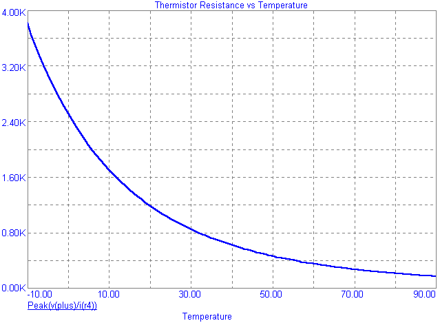
In this case, a transient analysis was simulated for 1us in which the circuit was stepped from -10C to 90C in 1C increments. The waveform plotted was v(plus)/i(r4) in which Plus was defined as the node at one end of the thermistor with the other end grounded, and R4 is a resistor in series with the thermistor. This waveform is equal to the thermistor resistance. The transient analysis was simulated with the Operating Point off so that the internal heating would not have an effect in the duration simulated. Once these runs were finished, a performance plot was created that plotted the peak of each of these runs versus the temperature that the run was simulated at. This produced the thermistor resistance vs temperature plot that appears below. Note that at the nominal temperature of 25C, the resistance is at its nominal value of 1Kohm.
For an AC analysis run, the thermistor's resistance must be constant. Therefore, there can be no ac effects from the internal heating. To avoid this, the TAU parameter must be set high so that the C1 capacitance will not cause the resistance to change during a simulation. This limits the resistance to being a function of RNOM, the ambient temperature, and the DC bias power portion of the temperature. A good rule of thumb is to set the TAU parameter to a value greater than 100/fmin where fmin is the minimum frequency being simulated.
|

|
|
|
|
|


