|
|
 |
Solving Differential Equations
Micro-Cap is of course known for its circuit simulation capabilities. However, the nature of SPICE's iterative process allows it to simulate many types of systems that can be modelled through standard equations and differential equations. This article covers the method of simulating spring systems that can be modelled with a single differential equation or coupled differential equations.
Single Differential Equation
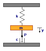
The system below consists of a mass, m, connected to a spring with a spring constant of k. A force P is applied to the system. A dashpot in the system produces a counteracting force of friction with a coefficient of friction c. The simulation will determine the displacement, y, of the mass due to the application of the force P. This entire system is governed by the differential equation:
m*y'' + c*y' + k*y = P
Both the displacement and the power will be considered in relation to time. After integrating the above equation twice and solving for y, the new integral equation produced is:
y(t) = (1/m)*S2(P(t)) - (c/m)*S(y(t)) - (k/m)*S2(y(t))
S is the integral operator and S2 is the double integral operator.
|
|
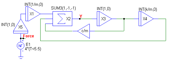
The circuit below implements this equation. The entire circuit consists of 4 INT macros, 1 SUM3 macro, 1 AMP macro, and a nonlinear function voltage source. The (1/m)*S2(P(t)) product is produced by the X5 and X1 INT macros. The X5 macro integrates the force the first time and then the X1 macro integrates the force the second time and supplies it with its 1/m coefficient. The output of X1 is then fed into the SUM3 macro.
The (c/m)*S(y(t)) product is produced by the X3 INT macro and the AMP macro. The X3 macro integrates the output of the SUM3 macro which is the displacement y. This signal is then fed into the AMP macro which multiplies it by the coefficient c/m. The INT macro doesn't supply the coefficient in this case, as it does in the other two products, because the output of the integrator is subsequently used to produce S2(y(t)). The resultant product is then fed into the SUM3 macro.
|
|
The (k/m)*S2(y(t)) product is produced by the X3 and X4 INT macros. The X3 macro integrates the displacement the first time and then the X4 macro integrates the displacement the second time and multiplies it with its k/m coefficient. The output of X4 is then fed into the SUM3 macro which along with the other two products produce the value of the displacement y of mass m at the output of the SUM3 macro. Whether the product is added or subtracted in the SUM3 macro is dependent on the gain parameters passed to the macro. In this case, (1,-1,-1) subtracts the second and third product.
The force applied to the system is produced by the E1 NFV source. This NFV source has its VALUE attribute defined as:
4*(T<5.5)
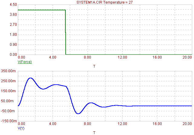
which will produce a 4V pulse for the first 5.5s of the simulation. This 4V pulse is the equivalent of a 4N force. The analysis results for this circuit appear below. For the simulation results, a 20s transient analysis was run. In this case, the system variables m, c, and k were defined as:
m = 4 kg
c = 5 N*s/m
k = 20 N/m
Both the force waveform, V(Force), and the displacement waveform, V(Y), were plotted. The value of zero for the displacement waveform is considered the equilibrium position when the mass is hanging with no external force acting on it. As can be seen in the plot, the displacement hits a maximum of .28 meters and eventually settles back to its equilibrium position once the external force is shut off.
|
|
Coupled Differential Equations
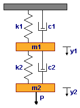
More sophisticated mechanical systems require the calculation of coupled differential equations. Modelling coupled differential equations uses the same procedure as modelling a single differential equation. The system below consists of two springs, two dashpots, two masses, and one external force.
|
|
The mass m1 is acted upon by two springs with spring constants k1 and k2 and two dashpots that provide the damping coefficients c1 and c2. The mass m2 is acted upon by the spring with constant k2 and the dashpot c2 along with the external force P. The differential equations that describe this system are as follows:
m1*y1'' + c1*y1' + c2*(y1'-y2') + k1*y1 + k2*(y1-y2) = 0
m2*y2'' + c2*(y2'-y1') + k2*(y2-y1) = P
After integrating the above equations twice and solving for y1 and y2, the new integral equations produced are:
y1 = (k2/m1)*S2(y2(t)) - ((k1+k2)/m1)*S2(y1(t)) + (c2/m1)*S(y2(t)) - ((c1+c2)/m1)*S(y1(t))
y2 = (1/m2)*S2(P(t)) + (k2/m2)*S2(y1(t)) - (k2/m2)*S2(y2(t)) + (c2/m2)*S(y1(t)) - (c2/m2)*S(y2(t))
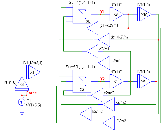
The circuit below implements these equations. The circuit consists of 6 INT macros, 8 AMP macros, an NFV source, and two macros, SUM4 and SUM5, that were created for this circuit. The SUM4 and SUM5 are just extended versions of the SUM3 macro that enable four products and five products, respectively, to be summed together.
|
|
The (1/m2)*S2(P(t)) product is produced by the X3 and X1 INT macros with the X1 macro providing the needed coefficient. The X9 INT macro creates the first integral of Y1, and the X10 INT macro creates the second integral of Y1. The X4 INT macro creates the first integral of Y2, and the X5 INT macro creates the second integral of Y2. The eight AMP macros provide the coefficients specified from the differential equations. The Y1 variable is created at the output of the SUM4 macro, and the Y2 variable is created at the output of the SUM5 macro. The gain parameters passed to the sum macros specify whether the product will be added (1) or subtracted (-1).
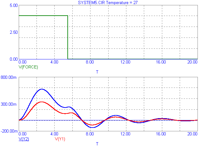
The analysis below displays the transient analysis results for a 20s simulation. Once again, the force for the system was created by an NFV source modelling a 4N force for 5.5s. The system variables for this mechanical system were set at:
m1 = 4 kg
m2 = 6 kg
c1 = 5 N*s/m
c2 = 7 N*s/m
k1 = 20 N/m
k2 = 25 N/m
The three waveforms plotted were the force, V(Force), the displacement of m1, V(Y1), and the displacement of m2, V(Y2). The equilibrium, with no external force P acting on the system for both displacement waveforms, is at zero. With the 4N force and the above variables, the maximum displacement for the mass m1 is .336 meters, and the maximum displacement for the mass m2 is .571 meters. Once the force goes back to zero, both displacement waveforms settle back into their equilibrium state.
The iterative process of SPICE is well adapted to handle simulations such as these. This technique can be used to plot any type of differential equations.
|
|
|
|
|
|


