|
|
 |
Importing and Exporting WAV Files
The Waveform Audio File Format (WAV file) is one of the most common file formats for storing uncompressed audio data in. Micro-Cap
has the capability to import this type of file as a voltage source input in a schematic and also to export a plotted waveform to
this audio format. Essentially, the input and output of a transient simulation can be an audio file. For example, a user can
input a WAV file into an audio amplifier schematic, and then listen to the output of the amplifier.
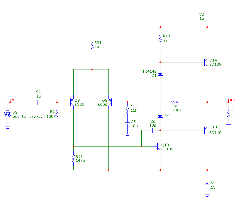
To demonstrate these capabilities, the WAVSource.cir file that is distributed with Micro-Cap 10 will be used. The schematic is shown
in the figure below. The circuit is a basic audio amplifier (Ref 1). The Q8 and Q9 transistors create the differential amplifier input
stage. The Q10 transistor operates as the gain stage with a common emitter amplifier configuration. Finally, the Q13 and Q14 transistors
operate as a push-pull output buffer stage. The input to this circuit is the V3 voltage source. This source is the WAV File Source
that is available in the Analog Primitives / Waveform Sources section of the Component menu.
|

|
The WAV File Source is the source that will import a WAV file to define the resulting voltage waveform. This source has the following attributes:
FILE: This attribute specifies the WAV file name and path that will be imported. For this example, the file specified is called Ode_to_Joy.wav.
This file contains a portion of Ludwig van Beethoven's song Ode to Joy from his Ninth Symphony.
CHANNEL: A WAV file can contain multiple channels. The number of channels can be as high as 65536 but a typical WAV file will often have just 2. A
WAV File source can only import one channel. This attribute determines which channel the source will import. The first channel is specified by the value 0.
SCALE: The WAV file data will be converted into a voltage waveform with a range of 1V to -1V. This attribute lets you scale the data to a different range.
REPEAT: This attribute determines the number of times that the WAV file data will be repeated during the transient simulation.
ENABLE_EXPR: This attribute defines a trigger expression that will initiate the waveform. The expression should be a boolean or conditional
expression. When the expression evaluates to True, the waveform will start playing. For example, if the waveform was to be delayed for 1s at the
beginning of the simulation, the expression T > 1 could be used which evaluates to True when the simulation time is greater than 1s. The default
value for this attribute is 1 which always evaluates to True.
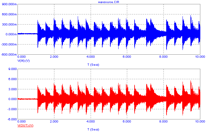
The resulting transient analysis for this circuit is shown in the figure below. The simulation time was set to 10s to get a good sampling of the music. The
top plot shows the voltage waveform produced by the WAV File source. The bottom plot shows the output voltage waveform of the audio amplifier circuit.
|

|
The output waveform looks like a good reproduction of the input waveform with a gain of approximately 20dB. At this point, the output voltage
waveform can be saved to a WAV file in order to listen to the output in order to notice any possible issues such as audible distortion.
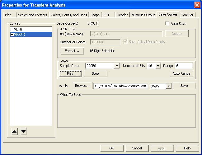
The Save Curves page within the Analysis Properties dialog box controls the settings for producing files from one or more plotted waveforms. The three
file formats available to create from this page are the Micro-Cap User Source files, Comma Separated Value (CSV) files, and WAV files. The Save Curves
page is shown below.
|

|
The list on the left hand side of the dialog box displays all of the waveforms that are available to be saved to a file. Clicking
on the box next to the waveform name enables or disables the waveform for the file.
For the WAV file, the .WAV section sets the format that will be used within the file. The Sample Rate field controls the number of samples
per second from the enabled waveforms that will be stored in the file. The list for this field displays the commonly used sample rates
for a WAV file, but the user can also type in their own custom sampling rate directly in the field. The Number of Bits field controls
the amount of bits used for each sampled data. The options are 8, 16, 24, and 32 bits. The Range field sets the amplitude range that
will be used to create the WAV data. In this example, the Range is set to 6 to ensure that all of the values from the V(Out) waveform
are stored in the WAV file without being clipped. If the Range was set to 1 for this waveform, any voltage value above 1 or below -1
would be clipped to the maximum value in the WAV file, and the resulting audio file would have a lot of distortion. The Auto Range
button scans the enabled waveforms and places the largest value of the waveform in the field. The Play button lets you hear the WAV
results without actually having to write the WAV file. The Stop button stops the WAV sample that is currently being played.
The In File section sets the file name and file type that is to be saved. For a WAV file, select .WAV from the extension list. The Save
button needs to be clicked to actually save the file to the hard drive. In the upper right corner of the page is an Auto Save checkbox.
When this is enabled, the file will automatically be created at the end of each simulation using the specified settings.
References:
1) "Basic Audio Amplifier", eCircuit Center, http://www.ecircuitcenter.com/Circuits_Audio_Amp/Basic_Amplifier/Basic_Audio_Amplifier.htm
|
|
|
|
|


