|
|
 |
Comb Filter Macro
A comb filter adds a delayed version of a signal to itself in order to cause either constructive or destructive interference to
the signal. Comb filters are used in a number of signal processing application such as CIC filters, television decoders, and
audio effects. There are two main types of comb filters: feed forward comb filters and feedback comb filters. The feed forward
comb filter adds a delayed version of the input signal to itself and is represented by the equation:
y(t) = x(t) + b * x(t - tau)
where b scales the delayed waveform and tau is the delay in seconds. The feedback comb filter adds a delayed version of the output
signal of the filter to the input signal and is represented by the equation:
y(t) = x(t) + b * y(t - tau)
Both of these comb filter types can be easily modeled in Micro-Cap using three macro components that are available in the program.
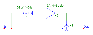
The figure below shows the circuit configuration for a feed forward comb filter. The circuit consists of a Delay macro, an Amp macro,
and a Sum macro. The Delay macro provides the delay on the input signal to the macro and models the tau variable in the first equation
above. The Delay parameter in the macro delays the input to the macro by a specified value in seconds. The output of the Delay macro
is then fed into the input of an Amp macro. The Amp macro simply scales the input to the macro by a constant specified in the Gain
parameter. This macro models the b variable in the feed forward equation. Finally, this delayed, scaled waveform is then summed with
the original input waveform by the Sum macro completing the model of the feed forward equation.
|

|
The feedback comb filter uses the exact same components but with a different configuration. The feedback comb filter appears in the
figure below. For this type, the Delay and Amp macros delay and scale the output signal of the filter. This modified signal is then
summed with the input signal to the filter to complete the feedback equation.
|
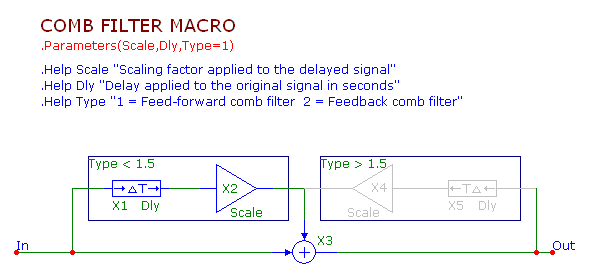
In order to make the comb filter easier to implement in a circuit, a macro circuit was created that can simulate either the feed forward
comb filter or the feedback comb filter. The macro circuit appears below.
|

|
The comb filter macro circuit has three parameters. The Scale parameter sets the value that the delayed signal will be scaled by. The
Dly parameter sets the time in seconds that the signal will be delayed. The Type parameter determines whether the feed forward or feedback
type will be used. When the Type parameter is set to 1, the feed forward comb filter will be used, and when the Type parameter is set to 2,
the feedback comb filter will be used.
The circuit uses a combination of both of the previous circuit configurations. The Scale parameter plugs in directly to the Gain parameter
of the Amp macros. The Dly parameter plugs in directly to the Delay parameter of the Delay macros. The macro circuit then uses the enable
region capability to switch between the feed forward type and the feedback type. An enable region uses a boolean expression to determine
whether the circuitry within the region will be enabled for a simulation. When the expression evaluates to True, then the circuitry will
be enabled, and when the expression evaluates to False, then the circuitry will be disabled. In this macro, an enable region has been drawn
around each of the Delay and Amp pairs. For the feed forward Delay and Amp pair, the enable region has been defined with the following
expression:
Type < 1.5
When the Type parameter is below 1.5, the circuitry within the region will be enabled. For the feedback Delay and Amp pair, the enable region
has been defined with the following expression:
Type > 1.5
When the Type parameter is above 1.5, the circuitry within the region will be enabled. Changing the Type parameter between 1 and 2 when using
the macro in a circuit just switches between the two configurations.
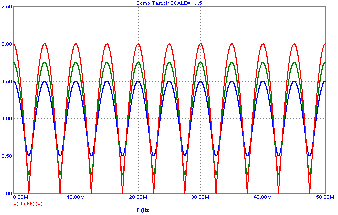
To see the frequency response of the comb filter, an AC analysis was run on a simple example circuit that just has a voltage source at the input
of the comb filter macro. The analysis plot below displays the frequency response of the feed forward comb filter where the macro parameters are set to:
Type = 1
Dly = 200n
Scale = Scale
where the Scale variable is set by a define statement. In the AC analysis, the Scale variable is then stepped through the values 1, .75, and .5. When
the scale value is positive, the local maximums in the frequency response occur at:
0, 1/Dly, 2/Dly, 3/Dly, ...
and the local minimums occur at:
1/(2*Dly), 3/(2*Dly), 5/(2*Dly), ...
With the Dly value set to 200ns, the local maximums occur at the expected 0Hz, 5MHz, 10MHz, 15MHz, etc, and the local minimums occur at the expected
2.5MHz, 7.5MHz, 12.5MHz, etc. If the Scale value is set to a negative number, then the maximum and minimum frequencies are swapped.
|

|
The analysis plot below displays the frequency response of the feedback comb filter. In this case, the macro parameters are set to:
Type = 2
Dly = 200n
Scale = Scale
In the AC analysis, the Scale variable is then stepped through the values .9, .75, and .5. For the feedback type, the comb filter is only
stable when the absolute value of the scale factor is less than 1. The local maximum and local minimum frequencies are calculated in the
same manner as the feed forward type.
|
|
|
|
|


