|
|
 |
Calculating VSWR, Return Loss, Reflection Coefficient, and Mismatch Loss
There are a number of calculations that are useful when simulating the transmission of a wave through a line.
These calculations can be quite important in calculating the energy that arrives at the load versus how much
energy the transmitter is producing. Ideally, the load impedance should match the characteristic impedance of
the transmission line so that all of the transmitted energy is available at the load. When the load impedance
does not match the characteristic impedance of the transmission line, part of the voltage will be reflected back
down the line reducing the available energy at the load.
One measurement is the reflection coefficient (Γ). The reflection coefficient measures the amplitude of
the reflected wave versus the amplitude of the incident wave. The expression for calculating the reflection
coefficient is as follows:
Γ = (ZL - ZS)/(ZL + ZS)
where ZL is the load impedance and ZS is the source impedance. Since the impedances may not be explicitly known, the
reflection coefficient can be measured in a similar manner to an S11 measurement by using the wave amplitudes at the
source and at the node following the source impedance. The following define statement user function can be used to
measure the reflection coefficient.
.define RefCo(In,Src) Mag(2*V(In)-V(Src))
where In is the node name of the node following the source impedance and Src is the part name of the source component.
The VSWR (Voltage Standing Wave Ratio) measurement describes the voltage standing wave pattern that is present in
the transmission line due to the phase addition and subtraction of the incident and reflected waves. The ratio is defined
by the maximum standing wave amplitude versus the minimum standing wave amplitude. The VSWR can be calculated from the
reflection coefficient with the equation:
VSWR = (1 + Γ)/(1 - Γ)
The following define statement user function can be used to measure the VSWR.
.define VSWR(In,Src) (1+RefCo(In,Src))/(1-RefCo(In,Src))
The return loss measurement describes the ratio of the power in the reflected wave to the power in the incident wave in units
of decibels. The standard output for the return loss is a positive value, so a large return loss value actually means that the
power in the reflected wave is small compared to the power in the incident wave and indicates a better impedance match. The
return loss can be calculated from the reflection coefficient with the equation:
Return Loss = -20*Log(Γ)
The following define statement user function can be used to measure the return loss.
.define RetLoss(In,Src) -20*Log(RefCo(In,Src))
The mismatch loss measurement describes the amount of power that will not be available at the load due to the reflected wave in
units of decibels. It indicates the amount of power lost in the system due to the mismatched impedances. The mismatch loss can
also be calculated from the reflection coefficient with the following equation:
Mismatch Loss = -10*Log(1 - Γ²)
The following define statement user function can be used to measure the mismatch loss.
.define MismatchLoss(In,Src) -10*Log(1 - RefCo(In,Src)**2)
For the VSWR, return loss, and mismatch calculations, the In and Src parameters are defined in the same manner as they are for
the reflection coefficient define statement.
If only the VSWR, return loss, or mismatch loss measurement is to be performed in the analysis, the reflection coefficient define
statement must also be present to perform the calculation since it is referenced in all three of these calculations.
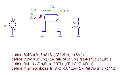
A simple circuit is displayed in the figure below to demonstrate the use of these define statement user functions. The circuit
consists of a voltage source, two resistors, and an ideal, lossless transmission line. The load resistance has been set to 75
ohms to create a mismatch with the 50 ohm characteristic impedance of the transmission line. The four define statement user
functions have been entered in the schematic as grid text. Each statement must be entered as a separate grid text. They may
also be entered in the Text page of the schematic to reduce the clutter in the schematic.
|

|
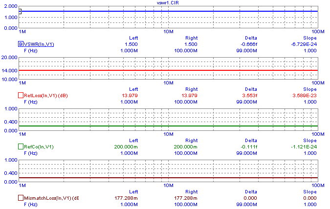
An AC analysis simulation is then run on the circuit. The four Y expressions plotted for the simulation are:
VSWR(In,V1)
RetLoss(In,V1)
RefCo(In,V1)
MismatchLoss(In,V1)
The AC simulation results are displayed below. Since this example circuit is entirely resistive, the AC analysis
response will be constant across the entire frequency range. Note that the node name used as the parameter within
these functions does not have to be named In. It can be any name that the user chooses or even the node number of
the node. V1 is the part name for the voltage source in the schematic.
|

|
The AC simulation returns the following results for this circuit:
VSWR = 1.5
Reflection Coefficient = .2
Return Loss = 13.979dB
Mismatch Loss = .177dB
The define statements can also be placed in the MCAP.INC file which can be accessed through the User Definitions
under the Options menu. Placing them in this file makes the functions globally available for all circuits.
Reference:
1) VOLTAGE STANDING WAVE RATIO (VSWR) / REFLECTION COEFFICIENT
RETURN LOSS / MISMATCH LOSS, Granite Island Group, http://www.tscm.com/vswr.pdf
|
|
|
|
|


