|
|
 |
Pulse Width Modulator Macro
One method to efficiently provide power for circuitry is through pulse width modulation (PWM). PWM switches
the power on and off in order to reduce the amount of power that is lost in the load. This modulation technique
produces a series of pulses whose duty cycle varies depending upon a reference signal. A low duty cycle
corresponds to when the power is off most of the time, while a high duty cycle corresponds to when the power
is on most of the time. The modulation signal used is typically a sawtooth or a triangle waveform. One method
to producing a PWM signal is the intersective method. When the reference signal is greater than the modulation
signal, the output is high. When the reference signal is less than the modulation signal, the output is low.
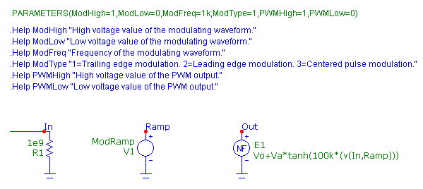
A PWM macro circuit using the intersective method appears in the figure below.
|

|
The macro circuit has two pins. The In pin is the input pin for the reference signal. The Out pin is the output
pin for the PWM signal. The modulation signal is generated within the macro circuit. The macro has six
parameters: ModHigh, ModLow, ModFreq, ModType, PWMHigh, and PWMLow. ModHigh and ModLow define the high and
low voltage values of the modulating signal. The ModFreq parameter defines the frequency of the modulating
signal. ModType defines whether the modulating signal is a trailing edge sawtooth, a leading edge sawtooth, or
a triangle waveform. The PWMHigh and PWMLow parameters define the high and low voltage values of the PWM output
signal.
The R1 resistor provides a DC path to ground at the input node. The V1 voltage source creates the modulation signal.
Its VALUE attribute is defined with the symbolic variable ModRamp which is set through the following series of define
statements in the Text page of the macro circuit.
.define ModPeriod (1/ModFreq)
.define ModTrans (ModPeriod/10000)
.if ModType==1
.define ModRamp Pulse ModLow ModHigh 0 {ModPeriod - ModTrans} {ModTrans} 0
+ {ModPeriod}
.elif ModType==2
.define ModRamp Pulse ModHigh ModLow 0 {ModPeriod - ModTrans} {ModTrans} 0
+ {ModPeriod}
.elif ModType==3
.define ModRamp Pulse ModLow ModHigh 0 {ModPeriod/2} {ModPeriod/2} 0 {ModPeriod}
.endif
The ModPeriod variable converts the ModFreq parameter into its equivalent period in units of seconds. The ModTrans
variable is used to set the transition time for the sawtooth modulation signal. It sets the transition time to the
modulation period divided by 10000. This creates a quick transition but provides a finite time in order to aid
convergence.
There are three define statements that define the ModRamp variable which creates the modulation signal. In all three
cases, the Pulse capability of the voltage source is used to create the signal. An If statement is used in conjuction
with the ModType parameter to determine which define statement will be used with the macro.
When the ModType parameter is set to 1, the first ModRamp statement is used. This statement creates the trailing edge
sawtooth waveform. The low voltage is set to ModLow. The high voltage is set to ModHigh. The rise time is set to the
modulation period minus the transition time. The fall time is set to the transition time, and the period is set to
ModPeriod. Both the delay time and the pulse width are set to 0.
When the ModType parameter is set to 2, the second ModRamp statement is used. This statement creates a leading edge
sawtooth signal. This operates similar to the first ModRamp statement except that the low voltage is set to ModHigh,
and the high voltage is set to ModLow.
When the ModType parameter is set to 3, the third ModRamp statement is used. This statement creates the triangle
waveform. The low voltage is set to ModLow, and the high voltage is set to ModHigh. The rise and fall times are
set to both be half of the period. The period is set to ModPeriod. Again, both the time delay and the pulse width
are set to 0.
Finally, the E1 NFV source creates the PWM output signal. The function source has been defined with the following
expression:
Vo+Va*tanh(100k*(v(In,Ramp)))
This creates a smooth transitioning comparator function which creates the pulse of the modulator. The hyperbolic
tangent operator produces a value between 1 and -1. The 100k provides a high gain that minimizes the transition
between the two limits. Essentially, when the differential voltage between nodes In and Ramp is positive, the tanh
function returns 1. When the differential voltage is negative, the tanh function returns -1. The Vo and Va variables
are set through the two following define statements.
.define Va (PWMHigh-PWMLow)/2
.define Vo (PWMHigh+PWMLow)/2
These two variables force the output voltage of the pulse signal to the high and low values of PWMHigh and PWMLow.
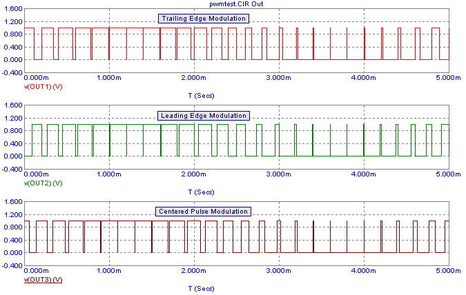
A simple circuit was created to demonstrate the different modulation types. Three of the PWM macros are placed in the
schematic. Each of the macros use the same reference signal which is a voltage source that has been set to produce a
200Hz sine wave that has a DC offset of .5V with an amplitude of .5V. The macros all share the following parameter
set:
ModHigh = 1
ModLow = 0
ModFreq = 5k
PWMHigh = 1
PWMLow = 0
The only parameter that is varied is the ModType parameter. Each of the macros has been defined to use a separate modulation
type. A 5ms transient simulation is run on the circuit. The results appear below.
|

|
The top plot shows the PWM output when the ModType parameter has been set to 1 so that the modulation signal is the trailing edge
sawtooth waveform. The middle plot shows the PWM output when the ModType parameter has been set to 2 so that the modulation signal is the
leading edge sawtooth waveform. The bottom plot shows the PWM output when the ModType parameter has been set to 3 so that the modulation
signal is the triangle waveform.
The corresponding modulation signals for the simulation are shown below. The top plot is the trailing edge sawtooth waveform. The middle
plot is the leading edge sawtooth waveform. The bottom plot is the triangle waveform. These modulation signals are plotted by
referencing the node Ramp within the macro circuit. For example, to plot the modulation signal within a PWM macro that has the part name
X1, the following expression is used:
V(X1.Ramp)
|
|
|
|
|


