|
|
 |
Balun Macro
The balun device is a type of transformer that can convert signals between balanced circuitry and unbalanced
circuitry. It is a bidirectional device so the signal conversion can go in either direction. The balun is
often used in communications and RF to provide compatibility between systems. A balun can be created in
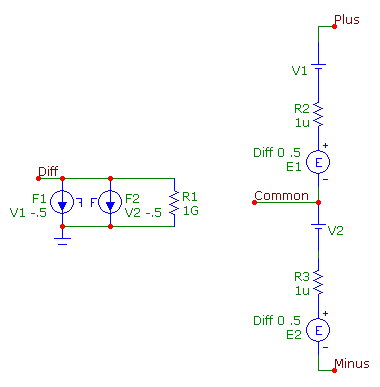
Micro-Cap by combining two ideal transformers. The balun macro circuit below was created based on a Ken
Kundert model described in Reference 1.
|

|
The macro circuit has four pins. The Diff pin is for the differential mode unbalanced signal. The Common
pin is for the common mode unbalanced signal. The Plus and Minus pins are for the balanced positive and
negative signals.
The macro circuit combines two ideal transformers. The first transformer consists of the F1 FIofI dependent
source, E1 EVofV dependent source, and the V1 battery. The V1 battery is used to measure the current into
the Plus pin of the balun. The F1 component senses the current through V1 and outputs a current of -.5*I(V1).
The E1 component measures the voltage at the Diff pin and outputs a voltage of .5*V(Diff). This transformer
is setup to provide a voltage gain of .5 from the Diff pin to the Plus pin. The second transformer consists
of the F2, E2, and V2 components and operates in the same manner as the first transformer. However, the
polarity on the balanced side of this transformer is reversed in order to create the negative signal at the
Minus pin. Since the macro is created from ideal components, the balun will work across all frequencies.
The voltage relationships for the balun are as follows:
V(Diff) = V(Plus) - V(Minus)
V(Common) = .5*(V(Plus) + V(Minus))
V(Plus) = V(Common) + .5*V(Diff)
V(Minus) = V(Common) - .5*V(Diff)
The corresponding current relationships are:
I(Diff) = .5*(I(Plus) - I(Minus))
I(Common) = I(Plus) + I(Minus)
I(Plus) = .5*I(Common) + I(Diff)
I(Minus) = .5*I(Common) - I(Diff)
The 1G ohm resistor at the Diff pin provides a DC path to ground at that node. The two 1u ohm resistors on
the balanced side of the balun prevent any possible voltage source/inductor loops that may occur when the
macro is used in a schematic.
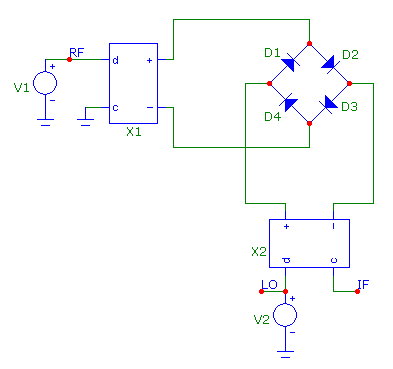
One application that baluns can be used for is in a double balanced mixer circuit. The double balanced mixer is
often used in microwave systems to down convert the frequency of an RF signal in order to process it. The RF
signal is combined with a local oscillator signal in order to output an intermediate frequency signal. An example
of a double balanced mixer is shown below.
|

|
The X1 balun has a 1GHz sine wave at its unbalanced pin to represent the RF signal. The balanced output is
connected across two nodes of a diode bridge. The X2 balun has an 870 MHz square wave as its unbalanced signal
which represents the local oscillator signal. The balanced outputs of this balun connect across the other two
nodes of the diode bridge. The Common pin of the X2 balun produces the intermediate frequency signal. The
combination of the RF and oscillator signals should produce an intermediate frequency signal of 130MHz.
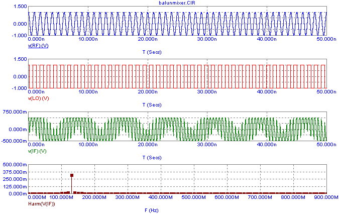
The mixer circuit is run in transient analysis with a simulation time of 50ns. The resulting simulation is shown below.
|

|
The top plot displays the 1GHz sine wave at the RF node. The second plot displays the 870MHz square wave at the LO
node. The third plot shows the intermediate frequency waveform that is created from the other signals at the IF node.
A low frequency sinusoidal waveform can be seen in the signal. The bottom plot displays the harmonics of the
intermediate frequency waveform by plotting the expression:
Harm(V(IF))
As expected, the harmonic plot shows that the fundamental frequency of the intermediate frequency waveform comes out at
130MHz.
References:
1) A Test Bench for Differential Circuits, Ken Kundert, Designer’s Guide Consulting, Inc., http://www.designers-guide.org/Analysis/diff.pdf
2) Double-balanced mixers, Microwaves101.com, http://www.microwaves101.com/encyclopedia/mixersdoublebalanced.cfm
|
|
|
|
|


