|
|
 |
RTD Macro
The resistance temperature detector (RTD) is a sensor that is commonly used to make temperature
measurements. The RTD can be made out of a variety of metals or alloys although platinum is the
typical material used. The RTD provides a stable, accurate temperature measurement as the
resistance of the RTD increases in a nearly linear fashion as the temperature increases.
The response of the resistance versus temperature is based upon the Callendar - Van Duesen
equation which is as follows:
R(Temp) = Rnom * (1 + A * Temp + B * Temp^2 + C * Temp^3 * (100-Temp))
For the popular Pt100 RTD, the above variables are defined as:
Rnom = 100 ohms
A = 3.9083m
B = -5.775e-7
C = -4.183p
where the value of the C coefficient is only applicable when the temperature is below 0C. Above
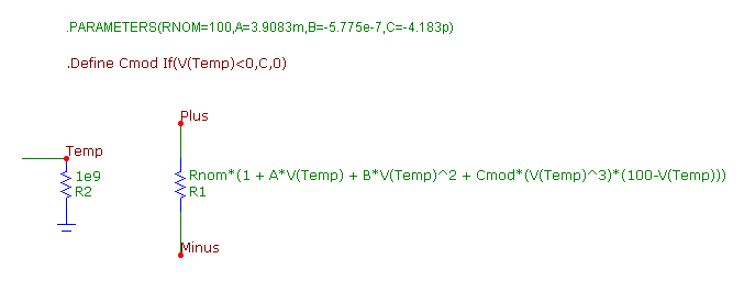
0C, the C coefficient has a value of zero. The schematic for the RTD macro appears in the figure
below.
|

|
The macro circuit has four parameters that are passed to it: RNOM, A, B, and C. The RNOM parameter
is the nominal resistance at 0C. The A parameter is the linear temperature coefficient. The B parameter
is the quadratic temperature coefficient. The C paramater is the quartic temperature coefficient.
The default parameters settings have been defined with the values specified for the Pt100 RTD device.
The macro circuit consists of two resistors. The R2 resistor simply provides a DC path to ground for the
Temp node. The voltage at the Temp node is equivalent to the temperature that the RTD component is measuring
using a direct 1V:1C ratio. The measured temperature for the RTD was setup in this manner to provide the
user the means of individually controlling the temperature of the device without affecting the other
components in the schematic.
The R1 resistor models the RTD resistance using the Callendar - Van Duesen equation. Its RESISTANCE
attribute is defined as:
Rnom*(1 + A*V(Temp) + B*V(Temp)^2 + Cmod*(V(Temp)^3)*(100-V(Temp)))
This expression has one slight modification versus the previously shown Callendar - Van Duesen
equation. Rather then using the C parameter directly, the Cmod parameter is used instead which
has been set through the following define statement.
.Define Cmod If(V(Temp)<0,C,0)
If the voltage at node Temp is less than zero, Cmod will be set with the value of the C parameter.
If the voltage at node Temp is greater than or equal to zero, Cmod is set to zero. This models the
temperature dependency of the C coefficient for the RTD. Note that the voltage at node Temp is used
as the temperature reference for the above two equations.
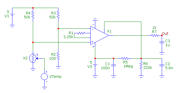
The schematic (from Reference 1) below demonstrates the use of the RTD macro. The circuit contains two
similar resistor dividers. One divider uses the Pt100 RTD device, X2, while the other uses an ideal 100
ohm resistor. The other half of each divider is a 50kohm resistor. A voltage source, VTemp, has been
placed at the Temp input of the RTD macro. This source will be used to define the measured temperature
of the RTD. At 0C, the two resistor dividers will produce the same voltage, but at any other temperature,
a voltage difference will arise between the two due to the varying resistance of the RTD. The junction of
each of these dividers is connected to the inputs of an INA326 instrumentation amplifier. The INA326
amplifies the voltage difference between the two dividers so that it can be used by devices such as ADCs.
|

|
A DC simulation is run on the circuit. The VTemp voltage source has its value linearly
swept from -200V to 850V. This is equivalent to sweeping the temperature of the RTD from
-200C to 850C. The simulation results appear below.
The top waveform displays the output voltage of the INA326 amplifier. The amplifier has
been configured to produce a voltage range of approximately 0V to 4V which is right in
line with the range of many ADC components.
The bottom waveform displays the resistance of the R1 resistor within the X2 RTD macro.
This is a direct plot of the RTD resistance. As can be seen in the plot, at 0C the
RTD resistance is at its nominal resistance value of 100 ohms.
|
Reference:
1) Developing A Precise Pt100 RTD Simulator For SPICE, Thomas Kuehl - http://www.analogzone.com/acqt_052807.pdf
|
|
|
|
|


