|
|
 |
Optimizing for Phase Margin
The phase margin measurement of an opamp circuit is one method of determining the stability of the circuit. At a
phase margin of zero, an opamp circuit becomes unstable. Even at small phase margin values, problems can occur
such as peaking in the frequency response or ringing in a step response. Typically a phase margin value of 45
degrees provides a safe margin to produce a stable opamp circuit.
The optimizer that is built into Micro-Cap is a great tool for optimizing circuit measurements such as phase margin.
The optimizer provides a simple method to determine the value of specific elements in the circuit to produce a stable
phase margin.
One common cause of low phase margin occurs when the opamp is driving a capacitive load. The output resistance of
the opamp combines with the load capacitance to create an additional pole in the circuit's transfer function. There
are numerous methods to stabilize a circuit that has a capacitive load. The method used in this article will be to
add an out of the loop isolation resistor between the output of the opamp and the capacitive load. The Micro-Cap
optimizer will be used on the circuit below to calculate the resistance value of the isolation resistor in order to
produce a stable phase margin.
|

|
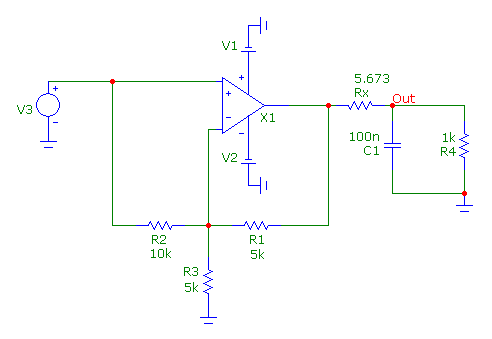
The circuit is a basic noninverting opamp circuit that has a gain of two. The opamp model used was created just
for this example. It uses the Level 2 opamp model with an open loop gain of 100k and an output resistance of
100 ohms. The opamp is driving a load that consists of a 1000 ohm resistor in parallel with a 100nF capacitor.
Note that the isolation resistor, Rx, is present in the circuit even though its value has been set at zero. The
optimizer will only operate on circuit elements that are already in the schematic. Since the isolation resistor
is set to zero, it will initially operate as a short circuit prior to the optimizer setting its value. The
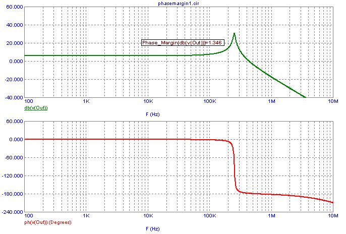
unoptimized frequency response of this circuit is shown below.
|

|
The phase margin is measured by determining the phase at the point that the gain curve
crosses zero. This phase value then has 180 degrees added to it to produce the phase margin
value. The performance tag in the top plot displays the phase margin of the circuit. To use
the Phase_Margin performance operator both the gain in dB and the phase of the desired output
must be plotted. Prior to opimization, the phase margin is barely above zero at 1.3 degrees.
Peaking can be seen in the gain curve as a result of the low phase margin. To ensure stability
with this circuit, the optimizer will be used to increase the phase margin to 45 degrees by
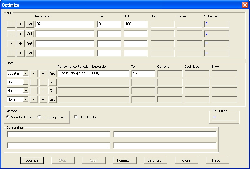
calculating a value for the isolation resistor. The settings for the Optimizer are shown below.
|

|
The Find section specifies the parameters to optimize. In this case, the part name of the isolation
resistor, Rx, has been entered. Rx has been given a range from 0 to 100 to find an optimized value
within. The That section specifies the performance criteria that the Find parameters will be optimized
for. The only criteria for this circuit is to set the phase margin to 45 degrees. The performance
function:
Phase_Margin(db(v(Out)))
is used. The Equates entry tells the optimizer to find the result that produces the closest fit to the
specified value of 45. A click on the Optimize button initiates the optimization. The optimizer
calculates that a value of 5.673 ohms for the Rx resistor will produce the desired 45 degree phase
margin. Hitting the Apply button modifies the schematic to use the calculated values.
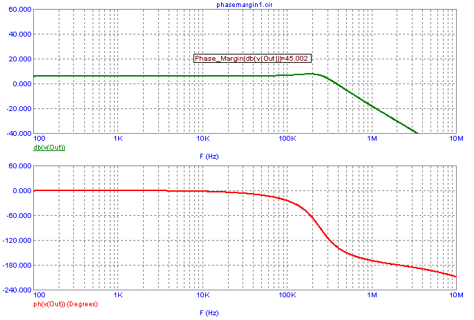
The optimized frequency response is displayed below. The phase margin is now at a stable value of
45 degrees. The peaking in the frequency response has also been greatly mitigated.
|

|
References:
1) http://www.analog.com/Analog_Root/static/techSupport/designTools/interactiveTools/stability/stability.html#applet
|
|
|
|
|


