|
|
 |
Simulating a PID Controller
The PID (Proportional-Integral-Derivative) controller is a common feedback mechanism used
within closed loop control systems. The controller is used to automatically adjust a
variable to keep a specified measurement at a set point. It can be found in applications
that need a form of temperature control, flow control, or position control.
The PID controller operates by comparing the set point versus the output measurement and
calculating the error between the two. The controller performs three calculations on the
error value. The proportional segment calculates the reaction to the current error value.
The integral segment calculates the reaction based on the history of the error value. The
derivative segment calculates the reaction based on how quickly the error value is
changing. The sum of these calculations is used to adjust the control system towards the
set point.
Each of the proportional, integral, and derivative calculations has a scale factor that
provides a weighting to the importance of that calculation in the controller output. An
increase in the proportional scale value will decrease the rise time and reduce the
steady state error, but too high of a value will lead to an unstable system. An
increase in the integral scale value will eliminate the steady state error but can lead
to an overshoot in the transient response. An increase in the derivative scale value
reduces overshoot and increases the stability of the system. Potential requirements of
the control system such as limiting overshoot also need to be taken into account when
determining the scale factors.
Simulating a PID controller is simple in Micro-Cap due to the behavioral macros that
come with the program. An example circuit that uses a PID controller to set the position
of a mass connected to a spring is displayed in the figure below.
|

|
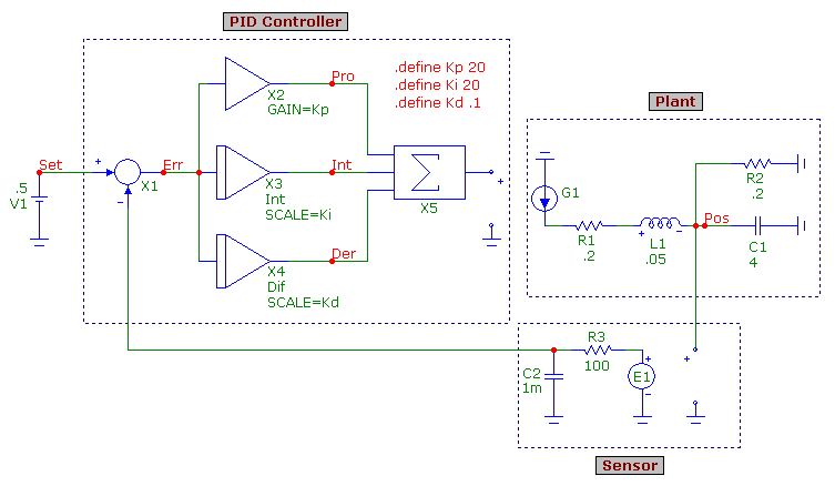
The PID controller is modeled using five macros. The Sub macro (X1) calculates the
difference between the set point value and the output measurement to produce the error
value. This error value is then fed into the proportional, integral, and derivative
inputs. The Amp macro (X2) calculates the proportional response. Its Gain parameter
has been defined with the Kp symbolic variable. The Int macro (X3) calculates the
integral response. Its Scale parameter has been defined with the Ki symbolic variable.
The Dif macro (X4) calculates the derivative response. Its Scale parameter has been
defined with the Kd symbolic variable. The three symbolic variables have their values
set using the following define statements:
.define Kp 20
.define Ki 20
.define Kd .1
Modifying the values in the define statements will tune the PID controller for the
specific application. The outputs of the Amp, Int, and Dif macros are then input into
a Sum3 macro (X5) which produces the PID controller output with which the control system
is adjusted.
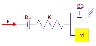
In this example, the PID controller is used to position a mass that is connected to a
spring by adjusting the force that is applied to the system. There are also a couple
of friction elements present in the system. The mechanical diagram of this control
system is displayed in the figure below.
|

|
In order to simulate this mechanical system in Micro-Cap, the elements need to be
converted into their electrical analogs. The force applied to the system is represented
by a current. Since this current needs to be adjusted by the PID controller, an IofV
dependent source (G1) is used where the voltage input to the source is the output of the
controller. The two friction elements, B1 and B2, are represented by resistors R1 and
R2. These resistors actually model inverse friction so the resistance values need to be
defined as 1/friction. The analog of the spring, K, is the inductor L1. The inductor
models the compliance of the spring so the inductance needs to be defined as 1/spring
constant. The analog of the mass, M, is the capacitor C1 connected to ground. The
capacitance is defined with the mass value. The voltage of the node between the
capacitor and the inductor is equivalent to the position of the mass in the system.
The sensor that performs the measurement of the mass position in this case is just a
simple VofV dependent source. For many control systems, the output measurement would
need to be converted into an appropriate unit to compare versus the set point.
However, since the output measurement and the set point value are on a direct one to
one ratio, the gain has been set to one for the dependent source. An RC time delay
was added to the output of the source to model a transport delay from the sensor output
to the feedback input of the PID controller.
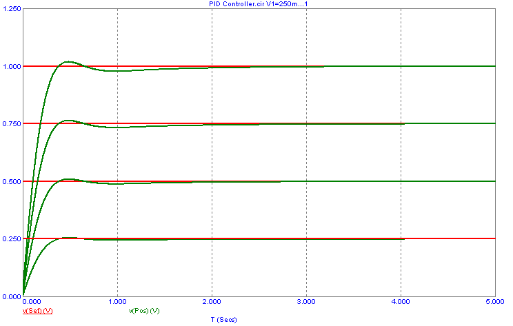
This schematic is then simulated in transient analysis. The V1 battery which defines
the set point value has been stepped from .25V to 1V in .25V increments, and the
simulation time is 5s. The resultant transient simulation is displayed below.
|

|
This simulation has the scale factors defined as Kp=20, Ki=20, and Kd=.1. Note that
the position of the mass will be adjusted so that it is equivalent to the set point
value in each branch of the simulation. There is a slight overshoot due to the
integral which can be eliminated by setting the Kd parameter to 1. Modifying these
scale factors will have a large effect on the transient response of the system so
the tuning of these values is very dependent on the control system that is being
adjusted.
|
|
|
|
|


