|
|
 |
DC Motor Macro
A common actuator used within control systems is the DC motor. The DC motor is
designed to generate mechanical energy in the form of torque from an electrical
energy input. Micro-Cap can model both the electrical portion of the motor as well
as the mechanical portion. To model the mechanical system of the motor, an
analogous electrical system is developed from the system equations. The macro
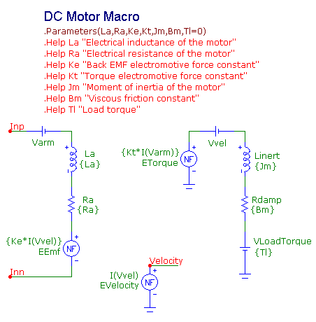
circuit of the DC motor appears in the figure below.
|

|
The macro circuit has seven parameters that are passed through to it: La, Ra, Ke, Kt, Jm,
Bm, and Tl. The La and Ra parameters define the electrical inductance and resistance
of the motor within its armature windings. The Ke parameter defines the back-emf
electromotive force constant. The Kt parameter defines the torque electromotive force
constant. The Jm parameter defines the inertia of the motor. The Bm parameter defines
the viscous friction constant. The Tl parameter defines the torque of the load.
The electrical system of the DC motor is represented by the following equation:
Vin = Ra * Ia + La *dIa/dt + Vemf
where Ia is the armature current that will determine the torque generated by the motor, Ra
is the electrical resistance of the motor, La is the electrical inductance of the motor,
and Vemf is the back-emf voltage. The back-emf voltage is the voltage generated as the
rotor of the motor moves through a magnetic field. As the velocity of the motor
increases, the back-emf voltage increases. This voltage counteracts the input voltage
of the motor. The back-emf voltage is calculated with the following equation:
Vemf = Ke * w
where w is the speed of the motor. The electrical system is modeled by placing an
inductor (La), a resistor (Ra), and a nonlinear function voltage source (EEmf) in
series. The EEmf function source has its VALUE attribute defined as:
Ke*I(Vvel)
where I(Vvel) is the electrical analog to the speed of the motor in the mechanical
system. The Inp and Inn nodes in the macro circuit are the input nodes to the voltage
differential that will drive the motor.
The mechanical system is defined by the following expression.
Tm = Jm * dw/dt + Bm * w + Tl
Tm is the torque generated by the motor. It is calculated with the following
expression.
Tm = Kt * Ia
The torque generated is the armature current multiplied by the torque electromotive
force constant. In the macro circuit, the torque is calculated through the NFV source
called ETorque whose VALUE attribute is defined as:
Kt*I(Varm)
where I(Varm) measures the current through a zero volt battery in series with the
armature circuitry.
The right hand side of the mechanical system equation has the same format as the
electrical expression of a series RL circuit. Jm is equivalent to the inductance.
Bm is equivalent to the resistance, and w is equivalent to the current through the
circuit. The Linert inductor and the Rdamp resistor in the macro circuit model this
part of the equation. The VLoadTorque battery is defined with the Tl parameter and
simulates a constant load torque placed on the motor shaft. The Vvel component is a
zero volt battery that measures the current, as an equivalent of the motor velocity,
for use in the back-emf source.
Finally, the NFV source named EVelocity is used to create a voltage equivalent to the
motor velocity. This voltage will be used as an output of the macro so that the motor
velocity is easily accessible in the main schematic. This output is useful if the motor
needs to be geared down, or the position of the motor needs to be determined by
integrating the velocity.
A simple circuit is created to test the motor macro. The circuit consists of a voltage
source that is used as the input to the DC motor macro. The voltage source has its
VALUE attribute defined as follows:
Pulse 0 10 0 1m 10m 999m 10
This source drives the motor with a 10V step voltage for one second. The values for
the DC motor macro parameters were taken from an article (Reference 1) that describes
a similar SPICE model for the motor. The macro parameters were set to the following
values.
La = 1.5mH
Ra = .5ohm
Ke = .05 V*sec/rad
Kt = .05 N*m/A
Jm = 250u N*m/rad/s^2
Bm = .1m N*m/rad/s
Tl = 0 N*m
This test circuit is run in transient analysis with a simulation time of two
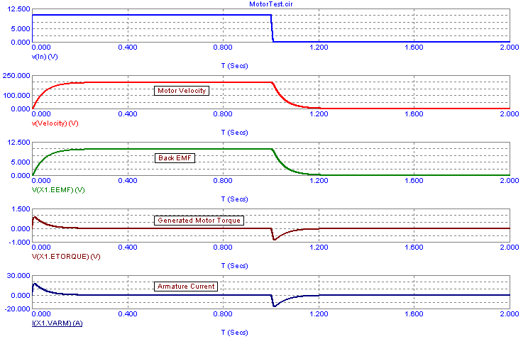
seconds. The resultant transient plots are displayed below.
|

|
The top waveform is a plot of the input voltage.
The second waveform plots the voltage at the Velocity pin of the macro which displays
the motor velocity.
The third waveform plots the back-emf voltage inside the macro by referencing the
voltage of the EEmf source. Note that X1 is the part name of the macro in the test
circuit.
The fourth waveform plots the generated motor torque by referencing the voltage of
the ETorque source in the macro.
The bottom waveform plots the armature current in the motor.
References
1) http://www.ecircuitcenter.com/Circuits/dc_motor_model/DCmotor_model.htm
|
|
|
|
|


