|
|
 |
Staircase Source Macro
The staircase source produces a waveform that strangely enough looks like a staircase.
This type of source waveform is commonly used in video and audio system simulation. It
can also be used in many D/A applications such as in linearity testing or testing
circuitry such as a digital amplitude modulator. There are a number of different ways to
create a staircase waveform. One can add the output of multiple pulse sources together,
use the output of a digital to analog converter, or use the PWL capability of the Voltage
Source component. Our solution is a simple and very flexible macro circuit for creating
a staircase waveform that is displayed below.
|

|
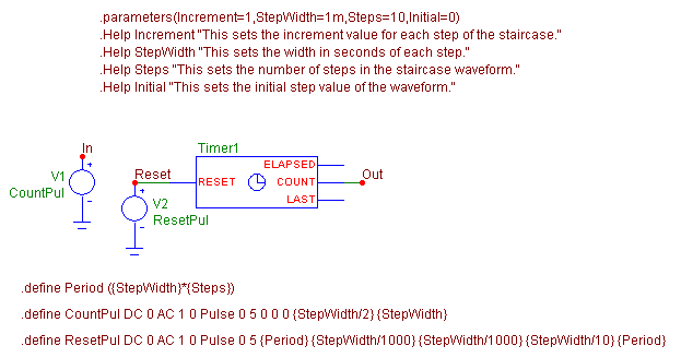
This macro circuit produces a periodic staircase waveform. The staircase macro has four
parameters that are passed to it: Increment, StepWidth, Steps, and Initial. The Increment
parameter defines the incremental voltage value for each step of the staircase. The
StepWidth parameter defines the width in seconds of each step. The Steps parameter
defines the total number of steps that the staircase waveform will consist of. The
Initial parameter defines the initial voltage value that the staircase will begin at
for each period of the waveform. The period of the waveform is calculated by multiplying
the StepWidth and the Steps parameters through a define statement.
The macro circuit consists of two voltage sources and a timer component. The first
voltage source, V1, defines the voltage at node In. The VALUE attribute for the source
has been defined as CountPul with a corresponding define statement of:
.define CountPul DC 0 AC 1 0 Pulse 0 5 0 0 0 {StepWidth/2} {StepWidth}
This statement produces a pulse with a 50% duty cycle whose period is equivalent to the
StepWidth parameter. The source rises immediately to 5 volts at the beginning of each
period, and then drops to 0 volts at the midpoint of the period. This source will be
used to trigger the counter that resides within the timer component.
The timer component is new to Micro-Cap 8. The timer is designed to monitor for a
specific event in the simulation. The timer counts the total number of events since
the start of the simulation or the end of the last reset pulse, the elapsed time since
an event occurred, and the last time the event occurred. For the staircase macro, only
the counting feature is of interest. The attributes for the timer are as follows:
INPUTEXPR = (V(In) > 2.5) * (t >= {StepWidth})
ELAPSED_SCALE = 1
INCREMENT = {Increment}
INITIAL = {Initial}
MIN = -1e9
MAX = 1e9
The INPUTEXPR attribute is a boolean expression that defines the event to be monitored.
In this case, it will record an event when the voltage at node In becomes greater than
2.5 volts and the simulation time equals or exceeds the StepWidth parameter. Since the
V1 source at node In creates a 5 volt pulse every StepWidth seconds, the count will be
incremented every StepWidth seconds. The simulation time requirement of the INPUTEXPR
attribute prevents the timer from recording the very first pulse in the simulation as
the V1 source will also create a 5V pulse at time = 0 which should be ignored by the
timer.
The ELAPSED_SCALE attribute is used to scale the voltage on the Elapsed pin of the
timer. This pin is not used in this macro.
The INCREMENT attribute defines the value that the count will be incremented by each
time a valid event is recorded. In this case, it is defined with the parameter
Increment that is being passed into the macro.
The INITIAL attribute defines the initial value that the count will be set to when the
simulation starts or when a reset pulse is triggered. In this case, it is defined with
the parameter Initial that is being passed into the macro.
The MIN and MAX attributes simply define the minimum and maximum values that the
counter is capable of counting to.
The current count value of the timer is produced as a voltage on the Count pin of the
timer. This count voltage models the staircase waveform.
The second voltage source, V2, is connected to the Reset pin of the timer. The VALUE
attribute for the source has been defined as ResetPul with a corresponding define
statement of:
.define ResetPul DC 0 AC 1 0 Pulse 0 5 {Period} {StepWidth/1000} {StepWidth/1000}
{StepWidth/10} {Period}
The Period variable used here is calculated by multiplying the Steps and StepWidth
parameters. This statement creates a five volt pulse every Period seconds after an
initial time delay of Period seconds. The pulse width is a tenth of the passed
StepWidth parameter which makes sure that the reset doesn't mask the next valid count
event. The Reset pin of the timer will reset the count value to its Initial value
whenever the voltage on the pin becomes equal to or greater than one volt. The V2 source
waveform produces the periodic capability of the staircase waveform.
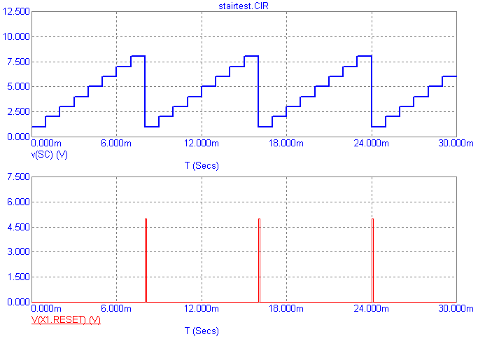
A sample transient analysis for the staircase source is displayed in below. The simulation
time is 30ms and the staircase macro's parameters have been defined as follows:
Increment = 1
StepWidth = 1m
Steps = 8
Initial = 1
|

|
The staircase produces the expected eight steps going from 1 volt on the first step to 8
volts on the final step before being reset. Note that the period of the staircase
waveform is 8ms (1m*8). The internal reset node voltage of the macro has also been
plotted with the expression:
V(X1.Reset)
where Reset is the node name inside the macro, and X1 is the staircase macro Part designator.
|
|
|
|
|


