|
|
 |
Using the Micro-Cap 8 IBIS Translator
The IBIS (Input/Output Buffer Information Specification) model format was developed by
Intel as a means to create analog models that represent digital integrated circuit I/O
characteristics. Many semiconductor manufacturers have IBIS files available as it
provides an accurate model that does not reveal proprietary process or circuit design
information. These models are most widely used for transmission line and signal
integrity analysis. One important note to make of these models is that they do not model
the internal logic of the specified device. They only simulate the I/O buffer structure.
The typical IBIS file contains the current and voltage characteristics, package parasitics,
and protection device characteristics of the I/O buffer structures. While IBIS files can
not be used directly in Micro-Cap, there is an IBIS translator available that will convert
these files into their SPICE equivalent. This article describes the process from having
the IBIS file to using the equivalent SPICE model in the schematic.
The IBIS Translator
The IBIS file used for this example was downloaded from the Philips Semiconductors
website. The file models the I/O buffer structure of the 74AHC00 quad 2-input nand
gate. The recommended location to place the IBIS file is in the Library directory of
Micro-Cap. Once you have the IBIS file in the desired folder, you can invoke the IBIS
translator by going to the File menu, clicking Translate, and then selecting the IBIS to
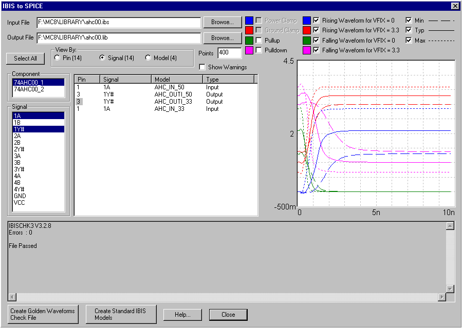
SPICE File option. The IBIS translator appears below. The Input File field should
specify the name of the IBIS file that is to be translated. The Output File field
specifies the name of the SPICE library file that will be created in the translation.
|

|
The next step is to select the models that are to be created in the translation. The View
By options determine the list of objects that are to be displayed. The Pin option displays
the list in terms of the pin numbers on the IC. The Signal option displays the list in
terms of the signal names of the IC. The Model option displays the list in terms of the
model names defined within the IBIS file. The Component field selects the part within
the IBIS file whose pins/signals/models will be displayed in the list. Typically, the
difference between the components are based on package variations. In this example,
the 74AHC00_1 defines the 74AHC00 component within a SO 14 pin package. The 74AHC00_2
defines the 74AHC00 within a TSSOP 14 pin package. This infomation can only be viewed
by opening the IBIS file in a text editor and reading the comments that are assigned to
each component. Below the Component field is the Item List which displays either the
pin names, signal names, or model names depending on the selection in the View By field.
Multiple items can be selected in this list by holding down the CTRL key when clicking on
a name. The IBIS List display is the large display in the middle of the translator.
This display shows all of the appropriate information for the items selected in the Item
List. The items within the IBIS List display will be the ones that have their equivalent
SPICE models created during the translation.
For this example, the Signal option has been selected in the View By field to display a
list of the signal names in the Item List. The Component selected is the 74AHC00_1. In
the Item List, the signals 1A and 1Y have been selected in order to create a typical
input and output for the device. Note that in the IBIS List, there are two entries for
each of the signals that have been selected. This particular IBIS file has data for the
74AHC00 component at two power supply voltages so models will be created using both the
5V and 3.3V power supply data.
The next step is to perform the translation to the SPICE models. Click on the Create
Standard IBIS Models button. A SPICE library file will be created at this point and
saved to disk. A second option is to click the Check Golden Waveforms Check File button.
This command is mainly used to test the data within the IBIS file. For typical system
testing the Create Standard IBIS Models command should be used. Click Close. The new
SPICE library will now be displayed in Micro-Cap.
The comment section at the top of the SPICE library will contain a section such as:
* Output Buffer Models:
* AHC_OUTI_50_3_TYPVCC
* AHC_OUTI_50_3_MINVCC
* AHC_OUTI_50_3_MAXVCC
* AHC_OUTI_33_3_TYPVCC
* AHC_OUTI_33_3_MINVCC
* AHC_OUTI_33_3_MAXVCC
*
* Input Buffer Models:
* AHC_IN_50_1_TYPVCC
* AHC_IN_50_1_MINVCC
* AHC_IN_50_1_MAXVCC
* AHC_IN_33_1_TYPVCC
* AHC_IN_33_1_MINVCC
* AHC_IN_33_1_MAXVCC
*
* Total: 12 Pin Models Created
These are the SPICE subcircuit models that have been created in the library to model the
IBIS information. For this component, six models have been created for each of the pins
that were selected. This is due to the fact that the translator will create minimum,
typical, and maximum models at each power supply for any selected pin. The subcircuit
name is produced from a combination of the IBIS model name, the power supply voltage,
the pin number, and the minimum/typical/maximum data. For example, the following
subcircuit name:
AHC_OUTI_50_3_MAXVCC
models the AHC_OUTI model at the 5V power supply for pin 3. It simulates the maximum
curve data of the IBIS file.
Adding the Subcircuits to the Component Library
The subcircuits now need to be placed in the component library for use in a schematic.
In the latest version of the Micro-Cap 8 component library, there are two generic
subcircuits called IBIS_In3 and IBIS_Out5. These provide a basic template for most
parts created through the IBIS translator. For those users that don't have these
subcircuits in their component library, download the files associated with this edition
of the newsletter. There are two files called IBIS.CMP and IBIS.SHP available. Place
these in the main MC8 directory. Enter the Component Editor and click the Merge icon.
Select the IBIS.CMP file as the file to merge. Click the Merge button. The two
subcircuits will be added to the component library.
Once these two components are available in your component library, adding additional
IBIS parts is easy. In the Component Editor, click on the Import Wizard icon. Enter
the name of the SPICE library that was created by the IBIS translator. Click the Next
button twice. Then click the Finish button. All of the IBIS subcircuits from the SPICE
library will be added to the component library. These parts are now available for
placement in a schematic. Since the SPICE library may contain many models, the Add Part
Wizard may also be used to add just a single subcircuit from the library instead.
IBIS Circuit Example
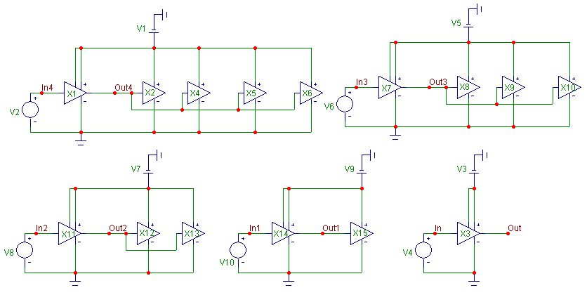
A sample IBIS circuit is displayed below. In this example, the 74AHC00 IBIS output
buffer is used to drive between zero and four of the 74AHC00 IBIS input buffers. For the
IBIS output buffers, the AHC_OUTI_50_3_TYPVCC model is used, and for the IBIS input
buffers, the AHC_IN_50_2_TYPVCC is used. Each of the pulse sources is a 1MHz 5V
pulse.
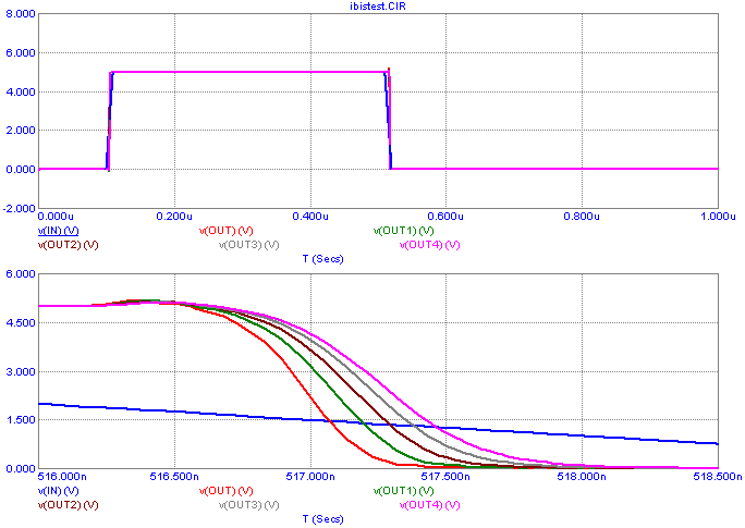
The resulting transient analysis is displayed below. The plots show a single input
waveform since all five are the same. Each of the five outputs is also plotted. The top
plot shows the entire simulation run. The bottom plot zooms in on the falling waveform
portion of the plot. As expected for each additional input buffer that the
AHC_OUTI_50_3_TYPVCC buffer drives, the load on that buffer is greater, and the resulting
fall time is increased.
This is a simplified example just to show the use of the IBIS buffers. A more complex
simulation could use transmission line models to take into account the length of the
wiring between each of the gates and would most likely need to use buffers from multiple
components.
|

|

|
|
|
|
|


