|
|
 |
Text Stepping of Model Statements and Subcircuits
A useful feature of stepping in Micro-Cap is the ability to step through specified text
strings. This feature can be used to step the model name or subcircuit name of a
component. This method provides a simple route to compare the output waveforms of a
schematic when different models are being used for the simulation.
Text stepping requires the use of a .define statement to declare the initial value of the
define variable. This initial value will be overwritten when the stepping is performed,
but it must be a model or subcircuit name that Micro-Cap will find and that is applicable
to the component. If the initial value doesn't adhere to these standards, then Micro-Cap
will return an error message. The define variable name must then be used to specify the
MODEL attribute, if you are stepping a model statement, or a NAME attribute, if you are
stepping a subcircuit.
To step this define variable, in the Stepping dialog box, the Symbolic Parameter Type
needs to be selected which provides a list of all symbolic parameters available to be
stepped. For text stepping, the List Method must be used since the Log and Linear
methods will obviously not be applicable when stepping a text string.
Stepping a Model Statement
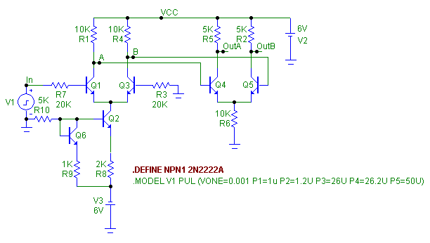
The schematic below displays a basic differential amplifier. There are six NPN
transistors within this amplifier configuration. Each of these transistors has had its
MODEL attribute defined as NPN1. A define statement has been added to the schematic
that states:
.DEFINE NPN1 2N2222A
|

|
Through this define statement, the MODEL attribute for all six
transistors is now set at 2N2222A which is a valid NPN model in
the Micro-Cap libraries. To step the model statement, an
analysis then needs to be entered. For this example, AC
analysis will be used. In the Stepping dialog box for the AC
analysis, the Parameter Type option has been set to Symbolic,
the Method option to List, and the Step It option to Yes. The
Step What and List fields are defined as follows:
Step What: NPN1
List: 2N1711, 2N2222A, 2N2218, ZTX869
The Step What field should be set with the name of the variable
in the define statement which was NPN1 in this case. The List
field is a comma delimited list of values. For text stepping,
these will be the names of the models that are to be simulated.
For this circuit, each of these model names must be the name of a
valid NPN model statement that resides locally in the circuit
file or in the libraries. These settings will produce four
analysis runs where the NPN transistors in each run are set to
one of the model names specified in the list field.
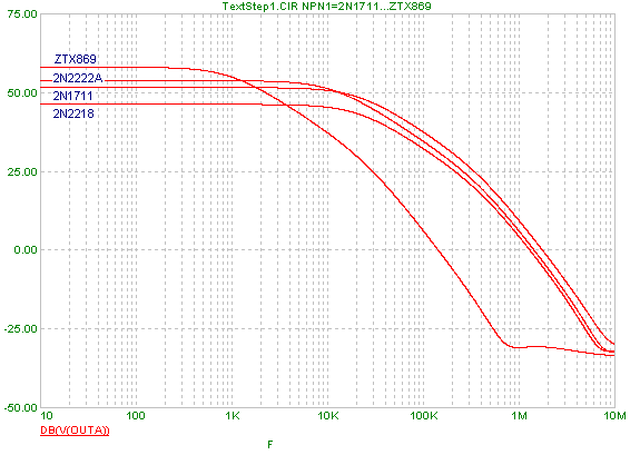
The resulting AC analysis is displayed below. The magnitude in
decibels of the voltage at node OutA is the waveform shown. Each
branch of the plot has been labelled with the name of the model
that produced the corresponding run. Note that the 2N1711,
2N2218, and 2N2222A are all basic general purpose transistors and
produce similar outputs. The ZTX869 transistor is a medium
power, high current transistor that has a smaller bandwidth and
higher gain compared to the other three transistor as is evident
in the plot.
|

|
Stepping a Subcircuit Name
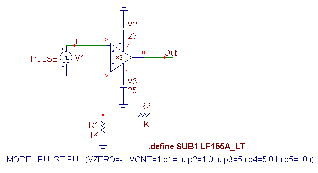
Stepping a subcircuit name is very similar to stepping a model statement. The schematic
below displays an opamp in a noninverting configuration with a gain of two that has a
pulse source as its input. The opamp in the schematic is a subcircuit component. Its
NAME attribute has been defined with the name SUB1, and there is a corresponding define
statement in the schematic that states:
.define SUB1 LF155A_LT
|

|
This defines the opamp as using the LF155A_LT subcircuit model. For this example,
transient analysis will be run. Again the Stepping dialog box settings have been set
so that the Parameter Type option is Symbolic, the Method option is List, and the Step
It option is set to Yes. The Step What and List fields are defined as follows:
Step What: SUB1
List: LF155A_LT, OP05E_LT, OP37A_LT
The Step What field has been defined with the name of the define variable referenced in
the subcircuit. The List field sets up the analysis so that it will produce three runs
with each run using one of three different opamp subcircuit models.
One item to be careful of when stepping subcircuit names is that any model referenced in
the List field must have the same pin layout as the subcircuit component that is present
in the schematic. If the Pin Names are displayed for the X2 component in the schematic,
it can be seen that they are defined as:
3 - Noninverting input
2 - Inverting input
7 - Positive power supply
4 - Negative power supply
6 - Output
All three subcircuit models referenced in the List field have their pin layout defined
such as:
.SUBCKT LF155A_LT 3 2 7 4 6
where the pins in the subcircuit model match the functions above. A subcircuit model
that uses different pin numbers or has a different amount of pins will return an error.
Note that if in the subcircuit model, pin 2 referenced the noninverting input and pin 3
referenced the inverting input, no error would be given because the pin names are the
same as in the X2 component, but the resulting analysis would not produce the expected
results since the inputs would be swapped when the simulation is run.
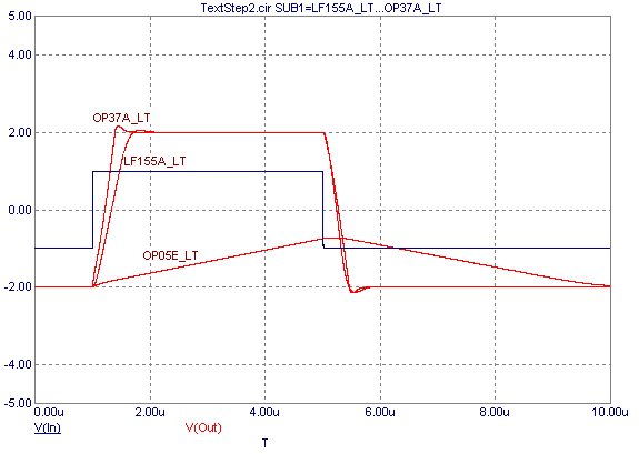
The transient analysis of this circuit is displayed below. The plot displays the opamp
output response to a 4us pulse at its input for each of the three subcircuit models
stepped. Each branch of the simulation has been labelled with the subcircuit model
name that produced the corresponding run. As can be seen in the analysis, the OP05E
opamp is too slow to pass the pulse through, but the LT155A and the OP37A opamps both do
a good job of reproducing the pulse with the specified gain at the output.
|

|
|
|
|
|


