|
|
 |
Digital Clock Macro
The digital clock macro provides a simple method for implementing a digital clock stimulus
in a schematic. It eliminates the complexity some people run into when trying to define a
clock stimulus in the traditional way.
The traditional way of defining a digital stimulus with a clock output is to use the
Stim1 component. This component is placed in the schematic and has its COMMAND attribute
defined with a symbolic name. Any valid text string may be used for the name. In this
case, we will use the name Clock. The symbolic name then needs to be specified using a
define statement such as the following:
.define Clock
+ Label = Start
+ 0ns 0
+ +50ns 1
+ +50ns Goto Start -1 Times
The define statement can be specified in the text area or directly within the Attribute
dialog box of the Stim1 component. In this case, the digital stimulus has been defined
as a clock with a 100ns period and a 50% duty cycle. At 0ns, the output of the clock is
set to a zero state. 50ns later, the clock output is set to a one state. 50ns after
that, the Start label is returned to and the sequence begins again. The 'Goto Start -1
Times' specifies that this loop will repeat forever.
The shortcut for this technique is to use the digital clock macro whose circuit is
displayed below.
|

|
The digital macro circuit consists of just one Stim1 digital stimulus source. There are
two parameters defined for this macro: Zerowidth and Onewidth. The Zerowidth parameter
defines the time in seconds that the clock will be at the zero state for each period of
the clock cycle. The Onewidth parameter defines the time in seconds that the clock will
be at the one state for each period of the clock cycle. The period of the clock cycle is
the sum of the Zerowidth and Onewidth parameters. The COMMAND attribute for the Stim1
source has been defined as CLOCK. In the text area of the macro circuit, there is a
corresponding define statement as follows:
.define CLOCK
+ Label = Start
+ 0 0
+ +Zerowidth 1
+ +Onewidth Goto Start -1 times
The two macro parameters are used here to define the transition times of the stimulus
output. In this case, the stimulus output starts at the zero state at time=0. After
Zerowidth seconds, the output transitions to the one state. In another Onewidth seconds,
the Goto statement is triggered and sets the stimulus output back to the zero state. The
Goto loop is set to repeat indefinitely.
That is the entire macro. While simple, it clearly demonstrates one of the advantages
of using macros in being able to simplify operations. Now, only two parameters need to
be specified to create a digital clock of any period with any duty cycle in a
schematic.
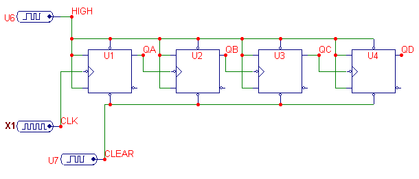
The digital clock macro is used in the circuit displayed below. The macro, X1, is used
as a clock input to the first JK flip-flop of a 4-bit binary counter. Standard Stim1
sources are used to define the digital waveform inputs for the Clear and Preset pins of
all four JK flip-flops. The digital clock macro has its parameters defined as:
Zerowidth = 40n
Onewidth = 60n
These parameters define a digital clock with a period of 100ns whose one state has a
60% duty cycle.
|

|
The resulting analysis is displayed below. The d(CLK) expression plots the output of
the digital clock macro. Two horizontal tags have been placed to show the period of
the clock and the width of the one state during that period. The width of the one state
is shown as 60ns, and the period is shown as 100ns which both match the specifications
defined for the macro.
|
|
|
|
|


