|
|
 |
Converting an Excel File to a User Source File
Some third party engineering software programs have the capability to output waveform data points
into an Excel Workbook format. In some cases, it can be very useful to use this waveform information
to define an input source in a Micro-Cap schematic. This article explains the process of how to convert
a voltage waveform that is contained in an Excel Workbook file into the file format that can be imported
by a User Source in a Micro-Cap schematic file for use in transient analysis.
|

|
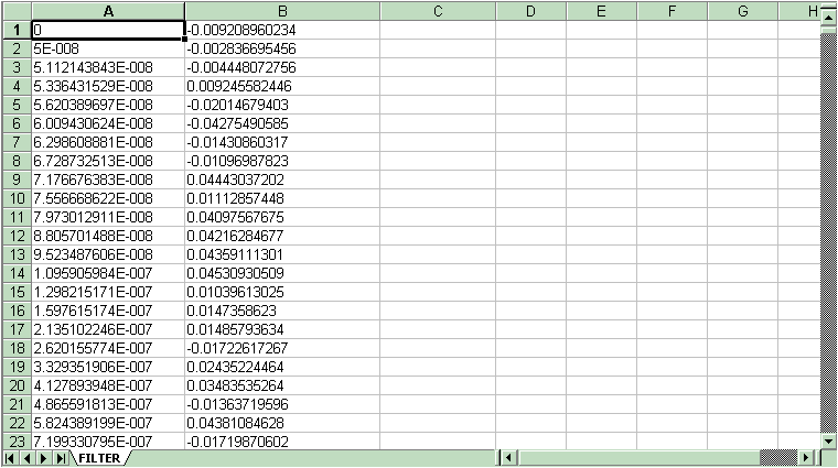
The figure above displays the data points of a voltage waveform within an Excel Workbook file. The first
column defines the time in seconds of each data point. When defining a User Source for transient
analysis, it is mandatory that the first column be time. The second column defines the value of the
voltage at each time point. Neither of these columns can be scaled. For example, the voltage column
must be in volts rather than millivolts or kilovolts, and the time column must be in seconds. The only
information that should be in both columns are the actual data points. Any headers at the top of the
column should be deleted.
The first step is to save the Excel file as a comma delimited text file. This is easily done by clicking
on File and Save As. In the Save As Type list box, there is a CSV (comma delimited) option. Select this
option and click Save. This converts the Excel Workbook format into a simple ASCII text file that has
the column data comma delimited. The file extension for the new file will be .CSV. It needs to be changed
to .USR. This change can be made in many ways such as through Wordpad or Windows Explorer. The .USR file
should then be placed in the directory that your Data path refers to.
The second step is to add the header information into the .USR file. The header information tells
Micro-Cap what type of information is in the file and the name of the waveform so that it can be processed
when an analysis is run. The header will appear as:
[Main]
FileType=USR
Version=2.00
Program=Micro-Cap
[Menu]
WaveformMenu=V(In) vs T
[Waveform]
Label=V(In) vs T
MainX=T
LabelX=T
LabelY=V(In)
Format=SimpleNoX
Data Point Count=1041
The [Main] section defines the format version that is being used. This section should appear exactly as
it is shown here for all User Source files.
The [Menu] section defines the names of the waveforms that are present in the file. Since there is only
one waveform in this file, there is only one WaveformMenu tag defined. In this case, the waveform is
called 'V(In) vs T'. Micro-Cap uses these tags to display the names of the waveforms in the file in both
the Attribute dialog box and in the Analysis Limits dialog box.
Each waveform in the file must have a [Waveform] section defined for it. This section defines the names
of the data columns and declares the format that the data is expressed in. The Label tag must match one
of the WaveformMenu tags in the [Menu] section. This tag contains the string that is to be defined in
the Expression attribute of the User Source when the source is placed in a schematic. The Format tag
defines the format that the data is in. In this case, SimpleNoX states that there will be only two
columns of data with the left column being time and the right column voltage (T,Y). Since the format
is SimpleNoX, both the MainX and LabelX tags will be defined as T for time, and the LabelY tag is defined
as V(In) for this waveform. The Data Point Count tag declares the number of data points the waveform
consists of. This number can be easily determined in Excel by the row number the file ends on. The
actual data points for the waveform should immediately follow the [Waveform] section.
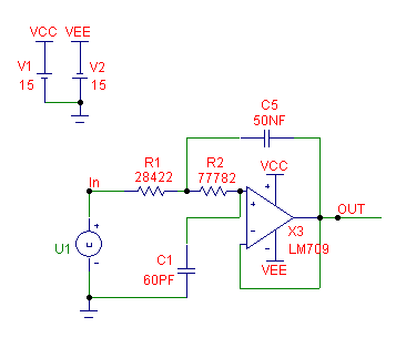
An example circuit that uses this new User Source file is displayed below. The user file that was created
for this example, FALL2002.USR, simulates a pulse with an injected noise source on top. The User Source,
U1, that references this file is fed into an active Chebyshev filter. The U1 User Source has its FILE
attribute defined as 'FALL2002.USR', and its EXPRESSION attribute defined as 'V(In) vs T'.
|

|
The resulting transient analysis of this circuit appears below. V(In) is the User Source input, and
V(Out) is the output of the filter. As can be seen in the analysis, the User Source is particularly
adapted to importing waveforms that can't be defined easily with standard sources or through
equations.
|
|
|
|
|


