|
|
 |
Digital Potentiometer Macro
A digital potentiometer performs the same function as a mechanical potentiometer or a variable resistor.
Instead of a mechanical wiper, the wiper position in a digital potentiometer is determined by the events
on logical inputs. Digital potentiometers have a few advantages over their electromechanical counterparts.
They can be used to handle a wide variety of specialty tasks that are not possible with the standard
potentiometer. Among these are remote process control, remote calibration, analog to digital conversions,
digital to analog conversions, variable gain amplification, and variable oscillation.
The digital potentiometer macro in this article was loosely based on the MAX5450-5455 series of devices from
Maxim. These devices are digital potentiometers with an up/down interface consisting of two fixed resistors
with 256 digitally controlled wiper contacts (taps). There are three digital inputs that determine the tap
point that will be accessible to the wiper. These digital inputs are INC, CS, and U/D. The INC input is
the wiper increment control input. A high to low transition on this input increments or decrements the wiper
position depending on the states of CS and U/D. The CS input is the chip select input. When this input is
low, the wiper position may be changed through INC and U/D. The U/D input is the up/down control input.
When this input is high, a high-to-low transition on INC increments the wiper position, and when the input
is low, a high-to-low transition on INC decrements the wiper position. If the wiper is at either the high
or low end of the resistor array, any increment or decrement in the direction of the endpoint will not
change the wiper position, so in other words, there is no wrap around effect. Finally, upon power-up the
initial setting for the wiper is at midscale (tap 127).
Macro Circuit
The basic modeling of the digital potentiometer macro consists of a 256 bit counter whose outputs are
sent to a DtoA converter. The output of the DtoA converter is then used to calculate the value of a
pair of resistors.
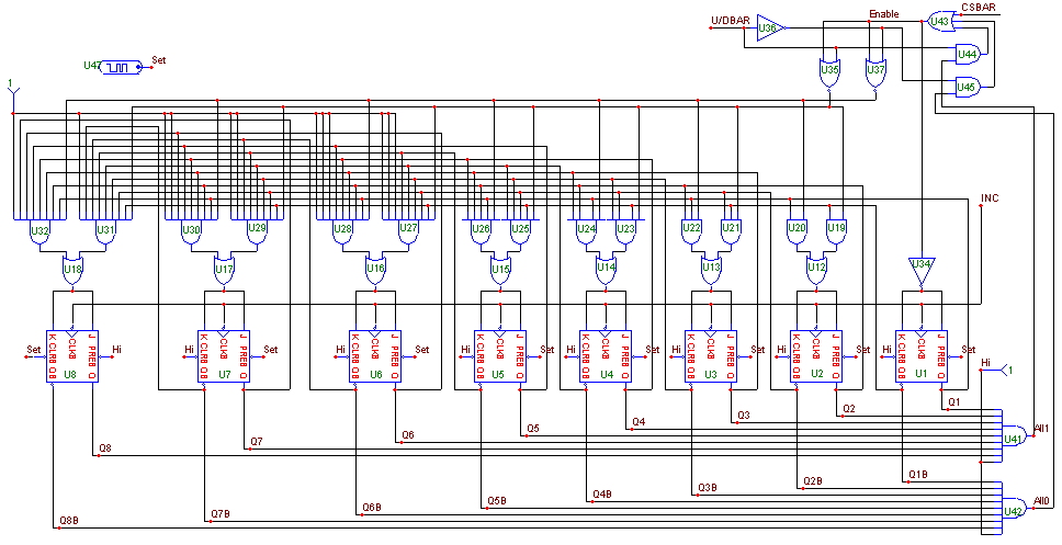
The 256 bit counter keeps track of the tap position the wiper is at. The counter used in the macro
appears below. The heart of the counter consists of 8 J-K flip-flops that store the tap position
on their non-inverting outputs. The INC input is fed directly into the clock inputs on each of the
flip-flops. The clear and preset pins of each flip-flop are connected to either the Hi node or the Set
node. The Hi node is at a constant one state that is produced by a Fixed Digital component. The Set
node waveform is defined by a digital stimulus which produces a short 10ns zero state that then returns
to the one state for the rest of the simulation. This waveform initializes the flip-flops. The U1
through U7 flip-flops are preset and the U8 flip-flop is cleared at the beginning of a simulation.
This sets the initial counter value to 127 to simulate the wiper being at midscale upon power-up.
|

|
The counter will be disabled under three instances. The first one is when the CSBAR input is set
high. The second one occurs when the U/DBAR input is set high and the non-inverting outputs of the
flip-flops are all high. This only occurs when the counter is trying to increment and the output
of the counter is already at 255 and thus prevents it from rolling over to 0. The third instance
occurs when the U/DBAR is set low and the inverting outputs of the flip-flops are all high. This
occurs when the counter output is at 0, and the counter is trying to decrement. It prevents the
rollover from 0 to 255.
The J-K inputs of each flip-flop are tied together. The logic that feeds into the J-K inputs controls
whether the flip-flop will toggle or remain in its current state at the next negative transition of
the clock. When the counter is incrementing, if all of the less significant non-inverting outputs are
high then the flip-flop will be set to toggle upon the next clock transition. When the counter is
decrementing, if all of the less significant inverting outputs are high then the flip-flop will be set
to toggle upon the next clock transition. Otherwise, the flip-flop will stay in its current state.
In both cases, the counter must be enabled for the flip-flop to toggle.
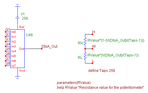
The non-inverting outputs of the flip-flops are fed into a DtoA component. The purpose of the DtoA
component is to convert the digital value of the counter into an analog voltage that the resistors can
reference to adjust their resistance values. The Reference node for the DtoA is a 256 volt battery.
The 256 volt reference causes the analog output to be equivalent to the value of the actual tap position
that is being assigned. For example, if the counter is pointing to the 87th tap position, the voltage at
the output of the node will be 87V. The advantage in this method is that it is easy to view which tap
position is being used when running an analysis. Simply plot the voltage at the node DtoA_Out within
the macro.
The two resistors of the potentiometer then use the output voltage of the DtoA component in determining
their own resistance values. When the counter is incremented, the resistance value of the RL resistor
is increased, and subsequently, the RH resistor value is decreased. The VALUE attribute of the RL resistor
is defined as:
RValue*(V(DtoA_Out)/(Taps-1))
and the VALUE attribute of the RH resistor is defined as:
RValue*(1-(V(DtoA_Out)/(Taps-1)))
RValue is the macro parameter that is passed through to the circuit. It represents the resistance value
for the potentiometer. The variable Taps is the number of taps in the potentiometer and is assigned the
value 256 through a .define statement. The three outputs of the potentiometer are the outputs H, W, and L.
These correspond to the high terminal, wiper terminal, and low terminal of the potentiometer. The DtoA
and resistor portion of the macro can be seen below.
|

|
Example Circuit
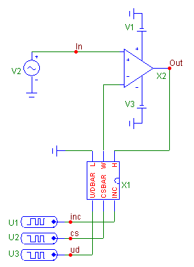
The example circuit for the digital potentiometer macro appears below. The opamp, a MAX402, is set up in
a basic non-inverting gain configuration. The opamp is powered by 5V and -5V power supplies and has a
1V, 10kHz sine wave going into the non-inverting input. The presence of the digital potentiometer in
the feedback provides a variable gain amplification for the circuit. The RValue parameter for the macro
is set at 10k. Three digital stimuli control the wiper position of the potentiometer. The .define
statements for each of the stimuli are as follows:
.define INC
+label=start
+0ns 0
+50ns 1
+100ns goto start -1 times
.define CS
+0 1
+10u 0
+14.2u 1
+280u 0
+288.5u 1
.define UD
+0 0
+14.2u 1
+48u 1
|

|
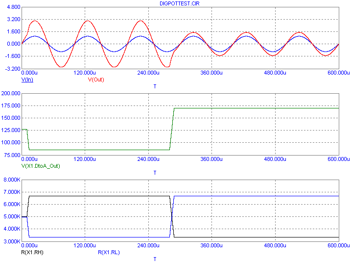
The transient analysis results for the circuit appear below. The top plot group displays the voltages at
nodes In and Out. The middle plot displays the voltage at the output of the DtoA component inside the
potentiometer macro, and the bottom plot displays the values of the two potentiometer resistors. The
simulation starts with the potentiometer at midscale (tap 127). From 10us to 14.2us, the wiper position
is decremented until it reaches tap 85. At this point, the RH resistor is at 6.667kOhms and the RL
resistor is at 3.333kOhms, and the gain of the opamp is set at 3. From 280us to 288.5us, the wiper
position is incremented until it reaches tap 170. The resistance of RH is now 3.333kOhms, the resistance
of RL is 6.667kOhms, and the gain of the opamp is set at 1.5.
|

|
Modifying the Macro Circuit
Not all digital potentiometers will use 256 taps for the wiper. If a potentiometer uses less taps, this
macro can be easily modified to simulate that device with three steps.
1) Change the inputs to the And gate in the counter whose output is at node All1. This And gate
determines the maximum value that the counter will go to using the outputs of the flip-flops. For
example, if you want to simulate 128 taps, you would replace the Q8 input with Q8B. The counter would
then go no higher than 127.
2) Swap the necessary Hi and Set texts on the prebar and clear nodes of the flip-flops to create the
initial power-up value. For example, if you want the 128 bit counter to power-up at midscale, you
would need to place the Set text on the clear pin and the Hi text on the preset pin of the U7 flip-flop.
The power-up wiper position would then start at tap 63.
3) Change the .define Taps statement so that Taps is set to the number of taps that will be used by the
device. For the 128 tap potentiometer, the statement should read '.define Taps 128'.
|
|
|
|
|


