|
|
 |
Introducing Micro-Cap 7
Micro-Cap 7 has just been released. It has a hoard of new features that are primarily targeted at enhancing ease of use. Many of the new features are derived directly from suggestions made by users. Here are snapshots of a few of the features:
Optimizer
An optimizer was added for use in transient, AC, and DC analysis, provided the capability of minimizing, maximizing, or matching numeric values for any set of performance function expressions subject to specifiable constraints.
|
RF models and Smith charts
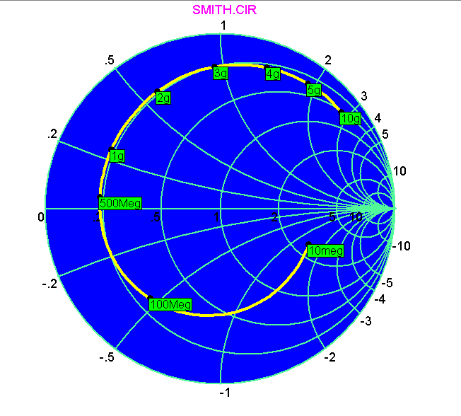
An S-Parameter two-port analog primitive was added to facilitate the modeling of RF devices. Smith chart and polar plot styles were added to simplify the plotting of S-Parameter data.
|
|
Portable schematic files
Formerly, to send a schematic to a colleague, it was sometimes necessary to transfer not only the schematic file, but the component library file, the shape library file, and any model library files used. In Micro-Cap 7, the schematic file format was expanded to include all information necessary to draw and analyze the circuit. The necessary component, shape, and model library information is stored in the schematic file, so sending a circuit to another user requires only circuit files be sent.
User-specified paths (folders) for all major file groups
User-specified paths (folders) for circuits and libraries were added to allow easy separation of file types. Circuits can be stored in one folder and model libraries in another. Formerly, circuit files and libraries had to be in the current (last opened) folder or in the folder set by the MC6DATA environmental variable.
Characteristic curves
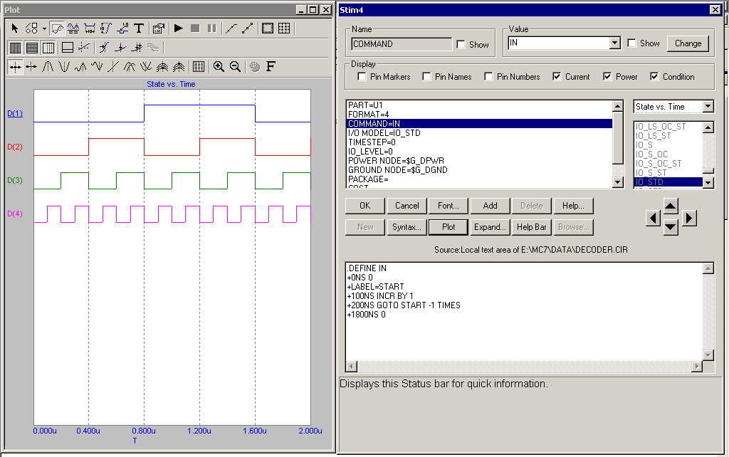
Many users have asked for a stimulus editor that would interactively show the waveform plot as edits are made. We liked the idea so much we added plots for most devices and incorporated it into the Attribute dialog box. Not just waveform sources, but active devices, diodes, Laplace sources, and digital stimulus sources all have characteristic curves or waveforms that can be plotted as you make edits. In the case of analog and digital waveform sources, the characteristic curve is the waveform itself. In the case of BJTs, one or more curves are selectable including DC current gain, saturation voltage, IV characteristics, and beta vs. frequency. Diodes and FETS have IV characteristics plots. OPAMPs have Bode plots.
|
|
Attribute dialog box editor
The Attribute dialog box (that comes up when you double-click on a part) was changed to allow editing of model parameters, subckts, digital stimulus patterns, and analog waveforms from within the dialog box. This makes the ADB the place for all-in-one viewing, editing, and visualizing model-related data for components.
|
Multistage undo and redo
A multistage undo and redo was added to let you go back and forth one or more schematic steps.
Improved component find command
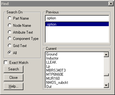
The component find command was expanded to search on the Name, Shape, Definition, and Memo fields. A Beginning of Line option was added to simplify Memo field searches. A text output of the search results was provided to create custom lists of the library sections.
|
|
Text stepping
Stepping through a list of text labels was added to facilitate automated analysis of multiple pattern names, subckt files, model statements, and other text based material. For example, if XYZ is the model name for a BJT, then stepping XYZ through the list {2N2222A, 2N3906, 2N4114} produces three runs each using a unique set of model parameters for the transistor.
Symbolic derivative finder
MC7 introduced the symbolic derivative finder. It solves for and prints symbolic derivative formulas. For example, it will find the derivative of x^x (x raised to the power of x), with respect to x, as x*x^(x-1) + x^x*ln(x).
|

|
Status bar monitor
The status bar was expanded to show electrical information such as part name, type, current, and power as the mouse passes over the schematic parts. It also shows the step values for waveform branches in the analysis plot.
Waveform and data point labeling
Optional, automatic labeling of stepped waveform branches was added. Labeling of data points from a user-specified list was also added.
|
Multiple file opener
A capability to open more than one file at a time was added. MC7 now opens one or more files selected from the File dialog box.
Smooth schematic panning
Smooth 1 pixel panning was added. Earlier versions panned 8 pixels to accommodate earlier, slower machines.
Bill of materials
A bill of materials was added to the program. It lists the number, value, power, cost, and instances, for each electrical part type in the circuit.
|
Sanity checker
A model parameter range checker was added to warn when model parameters exceed user-specified "reasonable" limits.
|
SPICE file probing
Probing, the ability to click on an object and see its curve or waveform, was added to SPICE text files. This was actually added after the original MC6 release and was never in the MC6 manuals.
Analysis plot improvements
Several improvements were made to analysis plots, including the ability to switch between log and linear scales, to select the grid interval and the grid pattern, width, and thickness.
Shape editor improvements
Several improvements were added to the analysis plots, including the shape origin symbols, font size memory, and a drag copy command.
Live formulas
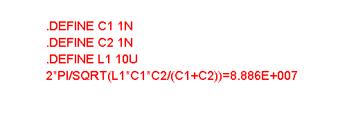
Live on-schematic text formulas were added that automatically update when any edits are made allowing live design formulas. Here for example is a live formula for the resonant frequency of a Colpitts oscillator.
|
|
New X and Y Scale format
A new scale format, High, [Low], [Step], allows users to specify arbitrary grid intervals (scale divisions). Panning a plot now maintains the minor grid structure for ease of use and readability.
|
Even decimal values cursor positioning
A new cursor positioning mode was added for placing the cursor on even decimal values of the horizontal axis variable.
Incremental auto-ranging
Y dimension auto-ranging was modified to apply only to the specified X range, not the whole simulation range.
Simultaneous multi-row analysis limits edits
Rapid analysis limits editing was facilitated by allowing users to change all of the rows in a waveform column simultaneously by clicking on the column header.
|
Run-invariant expressions in model parameters
Run-invariant expressions (those that don't change during a run) were added to model parameters. For example, a MOSFET VTO could be expressed as 2.0 + TEMP/100 to allow for threshold shift with temperature.
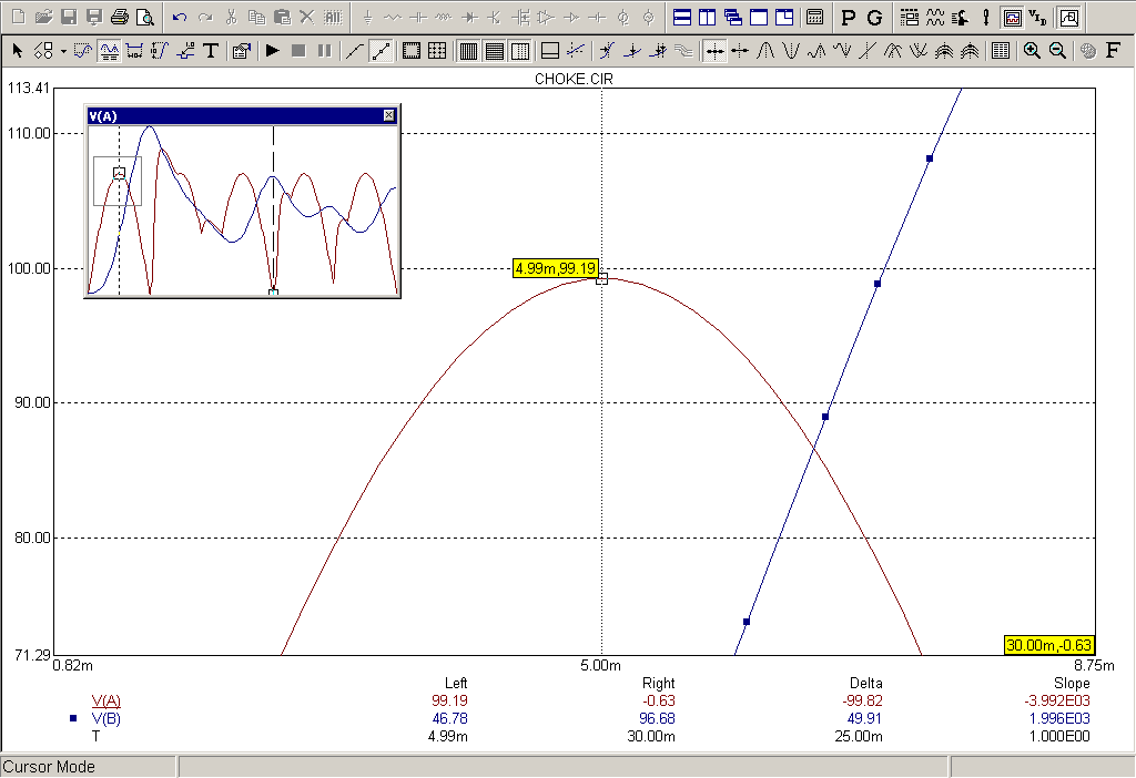
Thumbnail plot
A thumbnail plot was added to provide a global view of enlarged analysis plots, showing the location of the expanded region box superimposed on the whole plot.
|
|
Complex trigonometric functions
All trigonometric and hyperbolic expressions were modified to accept and return complex arguments. New trigonometric functions included cot, sec, csc, acot, asec, and acsc. New hyperbolic functions included coth, sech, csch, acoth, asech, and acsch.
Complex conditional functions
The MIN, MAX, and LIMIT functions acquired complex arguments.
Expressions for histograms and performance plots
In earlier versions of Micro-Cap, only individual performance functions were allowed. MC7 added individual performance function expressions as well. For example, expressions like Rise_Time(...) + Fall_Time(...) were allowed.
Attribute search and replace
A search and replace command was added to allow easy mass editing of model attributes.
PADS PCB output
The ability to write netlist files for interfacing to the PADS PCB program was added.
Energy variables
Stored, dissipated, and generated energy variables were added. Their format is similar to their power counterparts. EST is the total stored energy. EDT is the total dissipated energy. EGT is the total energy generated. Similar terms are available for individual parts. For example, ED(Q1) is the energy dissipated in Q1, and ES(Q1) is the energy stored in Q1.
New MOSFET noise terms
The standard PSpice noise terms, NLEV and GDSNOI, are now included in all MOSFET and BSIM models.
|
|
|
|
|


