|
|
 |
How to Build a Modulator /Demodulator
|
Ever wanted to build a modulator /demodulator circuit? It's simple. We'll demonstrate with this sample circuit:
|
In this circuit an NVF source is used to generate a test signal comprised of four sinusoids of frequency 200Khz, 500Khz, 1MHz, and 2MHz. The carrier sinusoid is supplied by a 50MHz sine source. The modulator is constructed from the MUL (Multiplier) macro, which is comprised of an NFV source that simply multiplies the two signals together. The demodulator is composed of a simple diode detector, followed by a low pass filter.
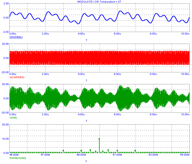
Here is the transient analysis, showing the input signal, the carrier, the amplitude modulated output (AM), and spectral components of the AM signal. The signal spectrum is centered at the carrier frequency of 50 MHz, with sideband components at +- 100KHz, +-500KHz, +-1MHz, and +-2MHz.
|

|
Here is the complete transient analysis, showing the input signal, the carrier, the amplitude modulated output (AM), and the recovered signal. The last plot shows the spectral components of the original signal and the recovered signal occur at the same frequency, and differ in magnitude by a factor of .1233.
|
|
|
|
|


