|
|
 |
Initializing a Flip-flop and Parts That Use Flip-flops
Flip-flops must be properly initialized before meaningful simulation results can be obtained. There are two general approaches to initialization:
• Using a STIM device to reset or preset the flip-flop during the first few nanoseconds of the run.
• Changing the DIGINITSTATE value to control the flip-flop initialization state.
Flip-flops are set to a value dictated by the value of DIGINITSTATE, which is set from the Global Settings menu, or by a .OPTIONS DIGINITSTATE = value command somewhere in the circuit. The initial state is set according to this rule:
|
Initialization Table
| DIGINITSTATE |
FLIP-FLOP INITIAL STATE |
| 0 |
0 |
| 1 |
1 |
| 2 |
X |
DIGINITSTATE set the flip-flop states to "0", "1", or "X" if its value is "0", "1", or any other value, respectively.
To illustrate the first method, consider this circuit:
|
|
Since there is no signal on the PREB or the CLRB input, and the flip-flop is being initialized to X, the output stays at X forever. Now consider this circuit:
|
|
Here we have connected an initializing pulse to the PREB input and connected the node with a fixed digital "1" to the CLRB (active low) input. As a result the flip-flop output initializes to "1" due to the "0" on the PREB (active low) input from the U3 STIM device. We could just as easily initialized the flip-flop output to "0" this way:
|
Here we have connected an initializing pulse to the CLRB input and connected the node with fixed digital "1" to the PREB (active low) input. As a result the flip-flop output initializes to "0" due to the "0" on the CLRB (active low) input from the U3 STIM device.
Note that we have used a digital STIM device and a fixed digital value to do the initialization. You could also use an analog pulse generator or an analog voltage as well. However, all-digital simulations are always faster than mixed-mode simulations, though for small circuits the differences are not significant.
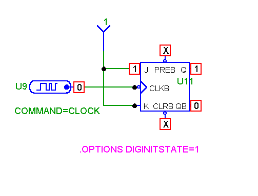
To illustrate the second initialization method, consider this circuit:
|

|
In this circuit there are no preset or reset signal sources on the PREB and CLRB pins. They aren't needed since the flip-flop is initialized to "1' by the command statement:
.OPTIONS DIGINITSTATE=1
This statement can be entered as grid text on the schematic, as shown here, or placed in the text area. The value of DIGINITSTATE can also be modified in the Global Settings, but doing that extends its effect to all circuits, whereas a command statement affects only the local circuit.
This general discussion of how to initialize flip-flops also applies to more complex parts that use flip-flops internally. For example, consider the 4040B circuit which uses an internal bank of twelve flip-flops:
|
Here we have initialized the CD4040B using a reset pulse that is "1" for the first 100ns and then changes to "0" for the remainder. Here is the transient analysis plot showing the expected initialization states due to the reset pulse.
|
|
Now consider the same circuit with the reset pulse removed and a command statement to set the value of DIGINITSTATE as follows:
|
Here we have initialized the CD4040B by setting the internal flip-flop states to an initial value of "1". Note that the Reset input must be set to an inactive state (0) using the fixed digital value device. Otherwise its initial X state would not allow counting.
Here is the transient analysis. Note that the run is slightly different that the preceding run. Here there is no reset to "0". Instead, all flip-flops are set to "1" as a result of the .options diginitstate=1 statement. On the first negative clock edge they all count to "0".
|
|
|
|
|


