


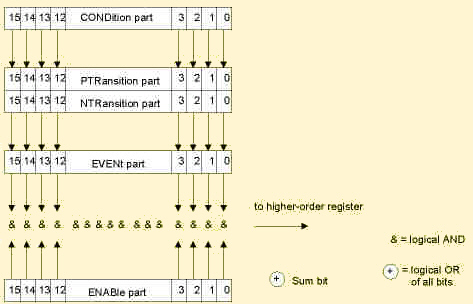
Each standard SCPI register consists of 5 parts which each have a width of 16 bits and have different functions. The individual bits are independent of each other, i.e. each hardware status is assigned a bit number which is valid for all five part. Bit 15 (the most significant bit) is set to zero for all parts. Thus the contents of the register parts can be processed by the controller as positive integer.
The status register model
| CONDition part | The CONDition part is permanently overwritten by the hardware or the sum bit of the next lower register. Its contents always reflect the current instrument status. This register part can only be read, but not be overwritten or cleared. Reading the CONDition register is nondestructive. |
| PTRansition part | The Positive-TRansition part acts as a transition
filter. When a bit of the CONDition part is changed from 0 to 1, the associated
PTR bit decides whether the EVENt bit is set to 1.
PTR bit =1: the EVENt bit is set. PTR bit =0: the EVENt bit is not set. This status register part can be overwritten and read at will. Reading the PTRansition register is nondestructive. |
| NTRansition part | The Negative-TRansition part also acts as a
transition filter. When a bit of the CONDition part is changed from 1
to 0, the associated NTR bit decides whether the EVENt bit is set to 1.
NTR bit =1: the EVENt bit is set. NTR bit =0: the EVENt bit is not set. This part can be overwritten and read at will. Reading the PTRansition register is nondestructive. With these two transition register parts the user can define which state transition of the condition part (none, 0 to 1, 1 to 0 or both) is stored in the EVENt part. |
| EVENt part | The EVENt part indicates whether an event has occurred since
the last reading, it is the "memory" of the condition part.
It only indicates events passed on by the transition filters. It is permanently
updated by the instrument. This part can only be read by the user. Reading
the register clears it. This part is often equated with the entire register.
The CMU implementation of the EVENt parts of all status registers differs from the SCPI specification: The bits in the EVENt part are directly set by the instrument as soon as the instrument state changes so that the setting condition becomes true. The CONDition, PTRansition, and NTRansition register parts are not needed. The EVENt part is cleared upon reading. |
| ENABle part | The ENABle part determines whether the associated EVENt bit
contributes to the sum bit (cf. below). Each bit of the EVENt part is
ANDed with the associated ENABle bit (symbol '&'). The results of
all logical operations of this part are passed on to the sum bit via an
OR function (symbol '+').
ENAB bit =0:the associated EVENt bit does not contribute to the sum bit ENAB bit =1:if the associated EVENT bit is "1", the sum bit is set to "1" as well. This part can be written into and read by the user at will. Its contents is not affected by reading. |
| Sum bit | As indicated above, the sum bit is obtained from the EVENt and ENABle part for each register. The result is then entered into a bit of the CONDition part of the higher-order register. The instrument automatically generates the sum bit for each register. Thus an event, e.g. a PLL that has not locked, can lead to a service request throughout all levels of the hierarchy. |
Note:
The service request enable register SRE defined in IEEE 488.2 can be taken
as ENABle part of the STB if the STB is structured according to SCPI.
By analogy, the ESE can be taken as the ENABle part of the ESR.