Connection via GPIB bus
The CMU is connected to the GPIB interface of the controller via the GPIB bus connector (IEEE 488 / IEC 625) at the rear of the instrument and a shielded cable. The technical specifications of the GPIB interface are listed in section "Hardware Interfaces " in Chapter 8.
GPIB Bus Configuration
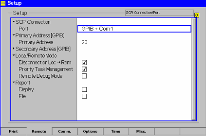
In the default configuration the CMU accepts commands from either the GPIB or COM 1 interface. The parameters for GPIB bus control of the CMU are set in the Remote tab of the Setup popup menu (in the following abbreviated by Setup – Remote, see also chapter 4, Settings for Remote Control).
Ø To open the Setup - Remote menu, press the SETUP key at the front of the instrument and activate the Remote hotkey at the lower edge of the screen.
Ø Use the rotary knob to move the focus onto the SCPI Connection section of the Setup table. If necessary, press the rotary knob or the ON/OFF key to expand the parameters in the table (see Chapter 3).
Ø In the Port table row select either GPIB + Com 1 or GPIB bus interface for transmission. The bus address is factory-set to 20. It can be changed in the Primary Address input field.
Connection via serial interface

The CMU can be connected to the serial interface of a controller via one of the serial interfaces COM 1 or COM 2 and a so-called null-modem cable. The pin assignment and wiring of a null-modem cable are described in section Handshake of chapter 8. The technical specifications of the serial (RS-232-C) interface are also discussed in chapter 8 (refer to section Hardware Interfaces).
Either a 25-pin or a 9-pin connector can be used on the controller side. It may be necessary to use an appropriate adapter (see chapter 8, Hardware Interfaces).
Selection
In the default configuration the CMU accepts commands from either the GPIB or COM 1 interface. The COM 2 interface must be selected explicitly.
Ø Proceed as described above to activate the Remote tab of the Setup menu.
Ø In the Port table row, select GPIB + Com 1 or COM 1 or COM 2 to activate one of the RS-232 interfaces for data transfer.
Configuration
After selection of a serial interface, the transmission parameters must be set to comply with the parameters of the addressed device. This is done in the Comm. (communications) tab of the Setup menu:
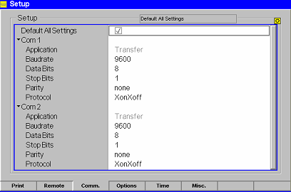
Ø To open the Setup – Comm. tab press the SETUP key at the front of the instrument and activate the Comm. hotkey at the lower edge of the screen.
Ø In the table section corresponding to the selected COM port check the settings for the Baudrate, Data Bits, Parity, and Protocol.